Installation Guide 10/100 Fast Ethernet Managed Switch with Fiber Connectivity KS-801 DOC.
Ó 2000 KTI Networks Inc. All rights reserved. No part of this documentation may be reproduced in any form or by any means or used to make any directive work (such as translation or transformation) without permission from KTI Networks Inc. KTI Networks Inc. reserves the right to revise this documentation and to make changes in content from time to time without obligation on the part of KTI Networks Inc. to provide notification of such revision or change.
9-Port Fast Ethernet Managed Switch with Fiber Connectivity INSTALLATION GUIDE DOC.
The information contained in this document is subject to change without prior notice. TRADEMARKS Ethernet is a registered trademark of Xerox Corp. This device complies with Class A Part 15 the FCC Rules. Operation is subject to the following two conditions: (1) This device may not cause harmful interference, and (2) this device must accept any interference received including the interference that may cause.
Table of Contents 1. Introduction ......................................................... 6 1.1 Features ............................................................................... 7 1.2 Specifications ....................................................................... 9 2. Installing the Switch ......................................... 10 2.1 Packing List ....................................................................... 10 2.2 Panels ........................................................
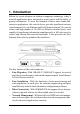
1. Introduction Driven by recent advances in desktop computing technology, todays network applications have increased in speed, power and the ability to process information. To meet the demands of these more bandwidthintensive applications, this switch device provides significant increase in performance for your Ethernet and Fast Ethernet network.
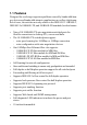
1.1 Features Designed for resolving congestion problems caused by bandwidth-hungry devices and bandwidth-intensive applications as well as a high number of users, the switches not only adhere to the IEEE 802.3 10BASE-T, IEEE 802.3u 100BASE-TX, and 100BASE-FX standards, but also feature: Nine of 10/100BASE-TX auto-negotiation switched ports for flexible connections to desktop PCs, servers and hubs.
Management Features: Telnet for remote control Provides one RS232 local console port IEEE 802.
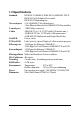
1.2 Specifications Standard IEEE 802.3 10BASE-T, IEEE 802.3u 100BASE-TX FX IEEE 802.3x Full duplex flow control IEEE 802.1D Spanning tree Network ports 9 10/100BASE-TX switched ports 1 Fast Ethernet fiber slot for 100BASE-FX fiber modules Console port 1 DB9 Male connector Cables 10BASE-T Cat. 3, 4, 5 UTP cable (100 meters max.) 100BASE-TX Cat. 5 UTP cable (100 meters max.
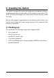
2. Installing the Switch The switch is designed to operate in workgroup environments without a complicated configuration procedure. It also features an auto-select 100240V, 50/60Hz power supply unit, which works in most countries around the world. Before connecting the supplied power cord into the switch, check to see that the cord voltage and current rating conform to the standards of the country of operation. 2.
2.
2.3 Mounting the Switches The switches can be placed on a desktop as a stand-alone unit. Allow enough ventilation space between the switch and the objects around it. Desktop Mounting For mounting the switch into a 19-inch rack, a pair of mounting brackets is included in the pack.
3. Making Network Connections 3.1 Network Switched Ports The following figure illustrates the switched ports provided on the switch. The switch comes with nine Fast Ethernet switched ports and Port #9 provides two connection types, one is 10/100BASE-TX RJ-45 connector and the other is 100BASE-FX fiber slot. The Fast Ethernet fiber slot can accommodate one optional Fast Ethernet fiber module.
10/100BASE-TX Fast Ethernet Switched Ports Each switched port supports one connection to a LAN segments. Each segment is an independent shared network in one collision-domain. The connection can be to either a 10BASE-T or a 100BASE-TX device. MDI-X and MDI RJ-45 Connectors MDI-X jack is labeled [X] normally to indicate the jack is designed with internal crossover function. It allows a connection to an end station using straight-through UTP cable.
3.2 10/100BASE-TX Fast Ethernet Ports The switch can support connections to the following devices: • • • • • 10BASE-T or 10/100BASE-TX network cards 10BASE-T hub ports 100BASE-TX hub ports 10/100BASE-TX dual speed hub ports 10/100BASE-TX switch ports Auto-negotiation Capable The ports support auto-negotiation function when establishing a link connection with any auto-negotiation capable device. The connection speed and duplex mode are determined through the negotiation process with the connected device.
Flow Control Half-duplex mode uses back pressure flow control to prevent the receiving buffer from being overrun by data from a source node. Full-duplex mode uses the 802.3X flow control standard to prevent fast Physical Ports data traffic from overrunning slow data traffic. UTP Cable Connections When making a connection to another device using straight-through UTP cable, make sure MDI-X to MDI connection rule is followed.
3.3 Fast Ethernet Fiber Slot The switch provides one fast Ethernet fiber slot. It can accommodate one optional fiber module for your fiber connection.
Module Outline The following figure illustrates an example of the fiber modules. Different type of modules is mounted with different fiber connector. Fiber Module (Top view) Fiber Jumper Setting The jumper group J1 on the module is used to enable or disable the fiber module.
Duplex Mode Setting The duplex mode used for the fiber module is configured by software port control settings. See chapter 5 for more information. Specifications Standard Speed Duplex mode Wavelength Fiber Connectors Fiber cable IEEE 802.3u 100BASE-FX 100Mbps Full duplex or half duplex 1300nm ST, SC, MT-RJ, VF-45 MM 50/125mm, 62.5/125mm recommended SM 9/125mm recommended Module Installation 1. Turn off the power to the switch unit. 2. Open the cover of Fiber slot. 3. Set Fiber jumper J1. 4.
3.4 Making Trunk Connections Two switch units can be cascaded together through any regular switched data port on each unit when a port expansion is required. However, the transfer bandwidth between the two cascaded ports is limited to 200Mbps full duplex. To increase the bandwidth for the connection between two switch units, a trunking function is implemented on the switch unit for this purpose. Normal data ports can be configured optionally as trunking ports through the network management operation.
The following figure illustrates an example of 2-port trunk connection between switch A and switch B. The aggregated bandwidth of the trunk is 400Mbps. Rules : 1. One switch can be configured to have up to 2 trunks and each trunk is composed of 2 trunking ports. 2. One trunking port can only belong to one trunk. 3. Only one trunk can exist between two switch units. 4. Crossover UTP cables should be used at the same time for one trunk connection. The length of each cable can be up to 100 meters. 5.
The following figure illustrates a typical example of trunk connections between three switch units. Each trunk is a 2-port trunk. There are two trunks existing in this example. Each has 400Mbps bandwidth. The top switch is configured to have two trunks and is cascaded to four lower switch units. 3.5 Making Sniffer The Port Sniffer is a method for monitor traffic in switched networks. Any switched port can be defined as a sniffer port which can monitor one or more port traffic.
4. LED Indicators 4.1 LED Panels The switch provides comprehensive LED indicators for diagnosing and monitoring the operation of the unit as illustrated below: 4.2 Interpretation Power LED : indicates the status of the power supplied to the switch. Link/Act. LED : indicates the port cable link and traffic activity. 10/100M LED : indicates the connection speed used Duplex/Col. LED : indicate the duplex mode used and collision status FX LED : indicate the fiber module is installed and active.
5. Performing Network Management 5.
5.
5.3 Setting IP Address Before performing any management operation over network, the most important thing is to learn the detailed information about the TCP/IP network where the managed unit is located. The information includes the network address, subnet mask, and IP of the default router. The second thing is to assign an IP address to the managed unit when it is received for the installation. A unique IP address is used to identify each managed device from others. Factory default IP address is 192.168.0.5.
Use the supplied RS232 cable to make the console connection directly from a PC COM port. The pin assignments of the connection are: Switch DTE console port 9-pin PC COM port Pin2 RXD -------------------------------3 3 TXD -------------------------------2 4 DTR -------------------------------6 5 GND -------------------------------5 6 DSR -------------------------------4 The console port does not support modem connection. 5.
5.7 SNMP Management SNMP management are performed at a network management station running SNMP network management application manager software with graphical user interface. The switch serves as an SNMP agent and provides the capabilities that allows network administrators to set parameters and view statistical counters defined in the standard MIB-II and private MIB. The supported MIBs are available in the supplied CD-ROM of the switch.
switch. TFTP is an embedded function supported in the DOS window of any Windows NT system. Console SFTP Utility 1. Connect your PC to the switch console port via PC COM port as specified in section 5.4. 2. Start the console management and select Update Firmware command from the main menu of console management screen. When message is shown on screen to indicate the switch is reday to receive file from console port. 3. Execute the utility program SFTP.EXE from your DOS window. 4.