
Owner's manual


Handbook BM 100 A 79
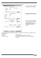
Appendix B: BM 100 A Level Gauge Configuration Record
For all service calls when a PC STAR record file or factory supplier data sheet is not available.
Fct.Nbr. Function Configuration Fct.Nbr. Function Configuration
1.1.0 Basic parameters
1.5.5 Epsilon R**
1.1.1 Tank Height
1.1.2 Hold Distance 1.5.7 Settling
1.1.3 Time Constant 1.5.8 Cleaning In Place
1.1.4 Window Frozen 1.5.9 Application Mode
1.1.5 Level Window
1.6.0 Serial Input /Output
1.1.6 Interface Window 1.6.1 Transmission Rate
1.1.7 Probe Length 1.6.2 Address (networks)
1.2.0 Display Functions 1.7.0 Volume Strap Table
1.2.1 Display Mode 1.7.1 Volume Unit
1.2.2 Display item 1.7.2 Strap Table Input
1.2.3 Cycle Time
1.2.4 Length Unit
Comments
1.2.5 Volume Unit
1.2.6 Error Message
1.3.0 Current Functions
1.3.1 Function I 1
1.3.2 Range I 1
1.3.3 Scale I 1 Min
1.3.4 Scale I 1 Max
1.3.5 * Function I 2 * if second output ordered
1.3.6 * Range I 2 ** for interface applications
1.3.7 * Scale I 2 Min
Strapping Table values (specify units) :
1.3.8 * Scale I 2 Max Pt Level Volume Pt Level Volume
1.4.0 User Data Functions
1 26
1.4.1 Language 2 27
1.4.2 Entry Code 1 3 28
1.4.3 Code 1 4 29
1.4.4 Device Number 5 30
1.4.5 Serial Number 6 31
1.4.6 French Comm No. 7 32
8 33 1.4.7 German Comm
No.
9 34
1.4.8 Option 10 35
1.4.9 Sensor Type 11 36
1.5.0 Application Functions
12 37
13 38 1.5.1 Level - first reading from display =
reflection amplitude
14 39
Gain Amplitude 15 40
16 41 - second reading from display =
threshold
17 42
Gain Amplitude 18 43
1.5.3 Detection Delay 19 44
20 45 1.5.4 ** Interface - first view from display =
reflection amplitude
21 46
Gain Amplitude 22 47
23 48 - second reading from display =
threshold
24 49
Gain Amplitude 25 50