
Owner's manual


Handbook BM 100 A 75
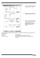
Record reading main screen
Item Item Description
1A & 1B (A) Current output 1/ level in mA/mm; (B) Current output 2/ interface level in mA/mm
2A & 2B Tank diagram showing current position of (A) level and (B) interface.
3 Dead zone limit
4A, B & C (A) Distance/ level of top product in mm, (B) Interface distance/ interface level of
bottom product 2 in mm, (C) Ullage volume/ volume in liters* (*configurable display).
5 Date of time slice
6 Time of time slice
7 F6: Trend function – shows level and interface over time recorded
8 F1: Help – on-line help function
9 F7 : Signal – shows return signal received by gauge at a given time and date
10 F2 : Configuration – access to user menu. The settings here are read-only. This list will
also show modifications to the gauge settings over the time measurement data is
recorded
11 F8 : Markers – Error indicators activated at a given time and date
12 F3 : Exit Record Reading window
13 F9 : Colors – change screen component colours as shown in Section 9.4.7
14 F10 : Screen copy – function for saving bitmaps of the current screen.
15 AltF1: Oscilloscope – to display signal amplitude/return signal time at a given day and
time.
16 +: playback functions