
Owner's manual


Handbook BM 100 A 45
4 Service and maintenance
4.1 Test Functions in the user menu
A series of tests are available in this part of the configuration menu. This permits the local display
and the instrument calibration to be checked.
Test Function Input range Description
2.0.0 TEST
2.1.0 TEST DISPL.
(TEST DISPLAY)
Gives full display of all
segments of the LCD display.
2.2.0 CUR OUTP.I
(CURRENT OUTPUT I)
2.2.1 VALUE I 1 N/a Gives a reading of current from
analogue output 1.
2.2.2 TEST I 1 Select 3.6, 4, 12, 20 or 22 mA. Forces the output 1 to a
selection of 4 output currents.
2.2.3 VALUE I 2 N/a Gives a reading of current from
analogue output 2.
2.2.4 TEST I 2 Select 3.6, 4, 12, 20 or 22 mA. Forces the output 2 to a
selection of 4 output currents.
2.3.0 COMM. TEST For factory use only.
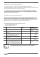
4.2 Troubleshooting
4.2.1 Parameter errors
Function Action to be taken
4 PARAMETER ERROR
4.1 CURRENT OUPUT
4.1.1 SCALE I 1 MIN
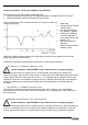
When a parameter error occurs, the digit 4 is displayed
with the description “PARAMETER ERROR”.
4.1.2 SCALE I 1 MAX
4.1.3 SCALE I 2 MIN
4.1.4 SCALE I 2 MAX
4.2 STRAP TABLE
4.2.1 STRAP TABLE INPUT
4.2.2 STRAP TABLE SUPRESS
4.2.3 DISPLAY MODE
4.2.4 DISPLAY ITEM
4.2.5 FUNCTION I 1
4.2.6 FUNCTION I 2
4.3 PARAMETERS ERRORS
4.3.1 DEAD ZONE
4.3.2 DETECTION DELAY
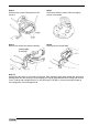
• The RIGHT key should be pressed until the function
concerned is given.
• Press the RIGHT key again to make the value appear
for modification.
• Follow the instructions for resetting the value in
Section 3 and then press ENTER to exit.
• If more than one error is reported, the procedure
should be repeated.