
Owner's manual


24 Handbook BM 100 A
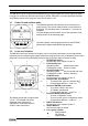
3.3 Status Markers
This line of numbers identifies six types of errors by means of a triangular indictor over the number
concerned.
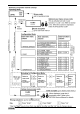
Status marker
number
Error / Status message Result and action
▼1 No initial pulse detected See section 4.3: Fault clearing.
▼2 No level reflection detected See section 4.3: Fault clearing.
▼3 Level measurement frozen Output and indication frozen; search initiated to
redetect level : if no reflection is registered :
Status marker 2 is activated.
▼4 No interface reflection found See section 4.3: Fault clearing.
▼5 Interface measurement
frozen
Output and indication frozen; search initiated to
redetect interface. If no reflection is found, Status
marker 4 is activated.
▼6 Output communication failure Contact your local KROHNE Service Department.
If the parameter 1.2.6 Error Display is configured to “YES” as explained in section 3.4.5,
the complete display screen will flash when an error occurs.
3.4 Parameter Settings
3.4.1 General Information
Your BM100 A has now been installed on the tank and the necessary electrical connections have
been made. Once the power has been switched on, it may be necessary to configure the gauge to:
• display the readings using the correct units and reference point (level / distance ),
• change the measurement range,
• give the instrument an address so that it may be integrated into a network,
• display volume readings by programming and using a volume calibration table (strap table).
We recommend that any changes to settings be noted on the configuration record supplied in
appendix B, or recorded using PC-STAR, to enable KROHNE service personnel to provide a rapid
response to any enquiries.
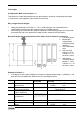
3.4.2 Configuration Procedure
The BM100 A starts up in operating mode displaying either information according to customer
specifications or factory default values.
The configuration mode (user menu) can be accessed and parameters modified by following the
operator control concept summary below. Configuration procedure is described in more detail in
section 3.4.3.
Instruments may equally be configured individually using a remote display available in PC-STAR
software for remote connections. Please refer to the PC-STAR on-line Help file for more details.
A restricted-access factory menu is available for advanced configuration. Refer to the BM100 A
Service Manual for further information.