© KROHNE 10/2001 7.02238.21.
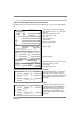
&RQWHQWV 3.1 Terminal compartment 3.2 Connecting cables 3.3 Connection of supply power and I/O functions 3.4 Connection of supply power 3.5 Options, current output 9 10 11 5 5 5 5 5 5 6 6 7 7 7 7 4 Initial start-up 12 5 Operation 12 6 6.1 6.2 6.3 6.4 Service / maintenance Signal converter Probes Replacement of complete device Maintenance 13 13 13 13 14 2 Installation 2.
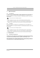
1DPHSODWH Signal converter without intrinsically safe I/O function Nameplate for the version with non-intrinsically safe I/O functions, such as current output, RS485, etc. 5()/(; 5$'$5 %0 L Type of protection; approved Gas Group and Temperature Classes, e.g.: EEx d [ia] IIC T6-T3 Approved Category: Ex II 1/2 DT 75…150°C or Ex II 1/2 G Type code Year of manufacture Serial number .52+1( 6 $ 5RPDQV )UDQFH ,, (([ .
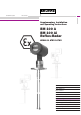
5DQJH RI DSSOLFDWLRQ The BM 100 A and BM 100 Ai Reflex-Radar level gauges are designed solely for measuring the distance, level,volume and interface of liquids, solids and particulate materials. They can be operated on storage and process tanks and also on still pipes and reference vessels. 3URGXFW OLDELOLW\ DQG ZDUUDQW\ Responsibility for suitability and intended use of these level gauges rests solely with the user. Improper installation and operation of our devices may lead to loss of warranty.
Section 1 – Main safety-relevant characteristics 0DLQ VDIHW\ UHOHYDQW FKDUDFWHULVWLFV 1.1 1.1.1 Approved categories 1/2 G and 1/2 D The signal converter is installed in hazardous locations requiring Category 2 G or 2 D equipment. The probe is installed in hazardous locations requiring Category 1 G or 1 D equipment. The devices are suitable for use in explosive atmospheres of all flammable substances of Gas Group IIA, IIB and IIC.
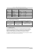
Section 1 – Main safety-relevant characteristics The connected equipment may not exceed the following maximum safety values: I/O function Marking Maximum safety values Passive current output Active current output Interface (1) PROFIBUS-PA Interface FF (1) Ui ≤ 30V Ci ≤ 5nF Uo ≤ 23.5V Co ≤ 110nF Ui ≤ 30V Ci ≤ 5nF Ui ≤ 30V Ci ≤ 5nF EEx ia IIC or EEx ib IIC EEx ia IIC or EEx ib IIC EEx ia IIC or EEx ib IIC/IIB EEx ia IIC or EEx ib IIC/IIB Ii ≤ 250mA Li = 10µH Io ≤ 98mA Lo = 3.
Section 1 – Main safety-relevant characteristics 1.4 1.4.
Section 2 - Installation / Section 3 - Electrical installation ,QVWDOODWLRQ In accordance with current installation standards for hazardous locations (e.g. EN 60079-14 / VDE 0165), assembly and installation may only be carried out by specialist personnel who have received training in explosion protection. The notes given in the standard Installation and Operating Instructions and in these Supplementary Instructions and the EC Type Test Certificate (see Attachment A.2) shall be observed without fail.
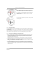
Section 3 - Electrical installation Type of protection EEx di or EEx ei Devices with intrinsically safe I/O functions must be provided with an additional separator in the terminal compartment. The separator is used for dividing the terminal compartment safely into an area for the supply lines and one for the I/O connection cables. Turn the separator upwards and to the side to wire up the I/O connecting cables. 3.
Section 3 - Electrical installation • Independent of the type of supply power, the device must be incorporated in the equipotential bonding system in the hazardous location. This can be done by way of an appropriately conductive connection between the device flange system and the tank. If connection to the equipotential bonding system is to be made via a separate conductor, this must be connected to the outer press-fitted U-clamp terminal on the signal converter flange.
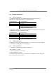
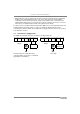
Section 3 - Electrical installation 3.5 Options, current output Options 1 to 7 apply to devices with intrinsically safe outputs (BM 100 A i) and to devices with non-intrinsically safe outputs (BM 100 A). Options 8 and 9 apply to devices with non-intrinsically safe outputs. Outputs with Intrinsic Safety type of protection may only be connected to certified feed devices.
Section 4 – Initial start-up / Section 5 - Operation ,QLWLDO VWDUW XS Disconnect from power before starting work! Check the following points before device start-up: • Do probe, flange and gaskets have adequate corrosion resistance to the tank product? • Do the data on the signal converter nameplate agree with your operating data? • Check that the measuring device has been properly installed on the tank.
Section 6 - Service / Maintenance 6HUYLFH PDLQWHQDQFH The device has no maintenance requirement when used for the intended purpose and in standard applications. 6.
Section 6 - Service / Maintenance 6.4 Maintenance Maintenance work of a safety-relevant nature within the meaning of explosion protection may only be carried out by the manufacturer, his authorized representative or under the supervision of authorized inspectors.
Attachments $WWDFKPHQW 10/2001 6WDWHPHQW RI &RQIRUPLW\ WR ,62 ,(& *XLGH BM 100 A ATEX 15
Attachments $WWDFKPHQW 16 (& 7\SH 7HVW &HUWLILFDWH .
Attachments 10/2001 BM 100 A ATEX 17
Attachments 18 BM 100 A ATEX 10/2001