
Manual


Installation and operating instructions
51
BATCHFLUX
Keyword Section-No. Fct-No.
N
Number format of display 5.4, 5.5 1.4
O
Operating pressure 10.5
Option = add-on equipment
= HHT 010
4.2, 6.1,
10.3-10.5 ,
Order numbers 9
Outputs
– connection diagrams 2.3
– characteristic 5.14
– setting 4.4
– I 5.6 1.5
– P 5.7 1.6
– S 5.8 1.7
Overflow display 5.5 1.4
P
P = pulse output 2.3.2, 4.4,
5.7
1.6
PC software 6.1
PCB =control electronics
PE = protective conductor 1.3.3, 2.1,
2.2
Power supply (= line voltage)
– connection 2.2, 10.5
– failure 4.5, 7.4
– frequency 2.2, 10.5
– power consumption 10.5
– voltage 2.2, 10.5
– changeover 8.2
Primary constant, see GKL 4.4, 5.11 3.2
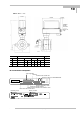
Primary head 1.4.1
– installation 1.1 - 1.3
– installation dimensions 1.3.1, 10.6
Printed circuit boards, see
PCB
8.9
Process temperature 1.1, 10.5
Program organization 4.1
Programming area, entry into 4.1 - 4.3
Programming = input 4.1 - 4.3
Protective rings 1.3.1
Pulse duration = pulse width 4.4, 5.7 1.6
Pulse output P / pulse width 4.4, 5.7 1.6
Pulses per unit volume/time 4.4, 5.7 1.6
Q
Q = flowrate 4.4 + 5.1 1.1, 3.2
Q100% = full-scale range 4.4 + 5.1 1.1, 3.2
R
R = reverse flow 4.4, 5.13 1.4 - 1.7
Range setting 4.4, 5.1 3.1.1,
3.1.2
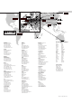
Removal of
– control electronics 8.3
– device (total) 1.4.2, 8.2
Reset totalizer 4.6
Return to
– functions column 4.1 - 4-3
– main menu column 4.1 - 4.3
– measuring mode 4.1 - 4.3
– submenu column 4.1 - 4.3
Reverse flow (R) 4.4, 5.13 1.4 - 1.7
RS 232 adapter 6.1
Keyword Section-No. Fct-No.
S
S = status output 2.3.2, 4.4, 5.7 1.7
Safety conductor PE 1.2.3, 2.2
Scope of supply 1.3
Signalling cable A 1.3.4, 10.4
Signal converter IFC 015
– connection, power 2.2
– connection, HHT 010 4.2, 8.9
– operator control 4.1 - 4.3
– spare parts 9
– error limits 10.2
– functional checks 7.1 - 7.3,
– technical data 10.4
SMU = low-flow cutoff 4.4, 5.3 1.3
Software 6.1
Special function = Option 6.1, 10.3-10.5
Status indication output 5.8
Status output S 2.3, 4.4, 5.7 1.7
Start-up 3
Straight outlet run 1.1, 1.2
Straight inlet run 1.1, 1.2
Storage 1.1,
Standards
– ANSI . . . 1.3, 10.3,
10.4, 10.6-10.8
– DIN . . . 1.2 10.3,10.4,
10.6-10.8
– EN . . 10.4
– EMC page 4
– IEC . . . 1.1,1.3.3,
10.3-10.5, 10.9
– VDE . . . 1.3.3, 2.1,
2.1, 10.4
Submenu column 4.1 to 4.3
T
T = time constant 5.2 1.2
Technical data
– measuring section / liners 10.3
– dimensions + weights 10.7, 10.8
– error limits 10.2
– limits for
liners 10.6
– signal converter IFC 015 K 10.2, 10.4
– primary head 10.5
Temperatures
– process product 10.3, 10.4, 10.6
– ambient 10.2 - 10.4
Tests, see functional checks 7.1, 7.2
Time constant (T) 5.2 1.2
Torques 1.3, 1.4.2
Totalizer (internal electronic) 5.7 1.6
Transport 1.1.1
U
Unit
– display 4.4, 5.4 1.4
– flow 4.4, 5.1 1.1
– pulse output 4.4, 5.7 1.6
User-definable unit 4.4, 5.12 3.5
V
v = flow velocity 4.4 + 5.1 3.2
Volumentric unit 5.12 3.5
Z
Zero check (adjustment) 7.1 3.3
E