
Manual


Installation and operating instructions 50 BATCHFLUX
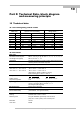
Part E Annex
E.1 Index
Keyword Section-No. Fct-No.
A
Abbreviations 4.4
ADC = analog/digital converter 4.5
Ambient temperature 1.1.1, 10.6
Analog/digital converter = ADC 4.5
ANSI flanges 1.2
B
Block diagram IFC 015 K 12
C
Cable lengths 2.2
Cermet electrode 1.3.2
Characteristic 5.14
Check elements 4.2
Cleaning 1.1.1, 8.1
Connection diagrams
– outputs 2.3
– power supply 2.2
Connection points
– grounding 1.3.3
– electricals (on housing) 1.4.1
Coding for Entry 5.11 3.4
CONFIG software 6.1
Conversion factor
– volume 4.4, 5.12 3.5
– time 4.4, 5.12 3.5
Current output I 2.3.1, 5.6 1.5
D
Data 4.4
–column 4.1-4.3
–error messages 4.5
Device description 1.4.1
Deletion of error messages 4.6
DIN flanges 1.3.1, 1.4-1,
10.4
Display 4.2 1.4
DN = meter size in mm 1.4, 5.5,
10.6,
3.2
E
Electrical connection
– outputs 2.3
– power supply 2.2
– status output 2.3.2
– current output 2.3.2
– pulse output 2.3.1
Electronic totalizer 5.4, 5.5 1.6
Electrodes 10.2, 10.6
EN Standards 1.1, 2.1
Error List 4.5, 4.6
Errors 4.5
Error (messages) 4.5
– cancel 4.5
– reset (delete) 4.6
– diagnosis, see functional
check
7. ff
F
F = forward flow 4.4, 5.3 1.4 - 1.7
Factory settings 3.2
Factor (time / volume) 5.12 3.5
Fatal Error 4.5
FE = functional ground 1.3.3, 2.1
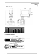
Flange spacing (fitting dim.“a“) 1.3.1, 10.6,
Flow (Q) 4.4, 5.1, 10.1 3.2
Flow velocity v 4.4, 10.1, 5.1 3.2
Flow, direction of 4.4, 5.1.1 3.2
Frequency output S
– pulse output P 2.3.3, 4.4, 5.7 1.6
Keyword Section-No. Fct-No.
Function of keys 4.1 - 4.3
Functional description page 5
Function(s) 4.4
Functional ground FE 1.3.3,2.1, 2.2
Function column 4.1,
Functional check 7.1 ff
– hardware info 7.3 2.2
– zero 7.1 3.3
– measuring range 7.2
Full-scale range Q100% 4.4, 5.1 1.1, 3.2
G
Gaskets 1.4.2, 10.3
GKL values 4.4, 5.11 3.2
Grounding 1.3.3, 2.ff
Guide collar 1.4.2, 1.3.2
H
Hand-held terminal HHT 010 4.2
Hardware info 7.3 2.2
I
I = current output 2.3.1, 5.6 1.5
IMoCom software 6.1
IMoCom bus (plug) 1.4.1
Impulses = pulses
Impulse output =
pulse output P
(frequency output) 2.3.2, 5.7 1.6
Input
– of entry code 5.11 3.4
– programming 4
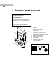
Installation of primary head 1.ff
Instrument nameplates 10.7
Interface RS 232 6.1
internal electronic totalizer 5.5 1.4
Interface adapter RS 232 6.1
K
Keys 4.1 - 4.3
Keystroke combinations for
– entry into setting level 4.1 - 4.3 3.4
– error cancelling 4.6
– quitting the setting level 4.1 - 4.3
– resetting totalizer(s) 4.6
L
Language of display texts 5.9 3.1
LCD display, see display 4.2, 4.4, 5.4 1.4
Limits 10.5
Liner 10.6
Liner / measuring section 10.2, 10.6
Line voltage, see power supply
Low-flow cutoff 4.4 + 5.3 1.3
Low-flow cutoff “off“ value 5.3 1.3
M
Main menus 4.1 - 4.3 1.0, 2.0,
3.0
Main menu column 4.1 1.0, 2.0,
3.0
Magnetic field frequency 4.4, 5.11 3.2
Materials of construction 10.2, 10.6
Menu 4.1, 4.4
Measuring principle Page 5
Measuring tube 10.6
Metal pipeline, grounding of 1.3.3, 2.1
Meter size (DN) = nominal dia.
of measuring tube in mm or 4.4, 10.3, 3.2
inches 10.4
E