
Manual


Installation and operating instructions
35
BATCHFLUX
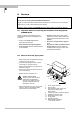
5.13 F/R mode, forward / reverse flow measurement
•
Refer to Sect. 2.3 for electrical
connection of the outputs.
•
Define direction of forward (normal)
flow, see Fct. 3.2, subfunction “FLOW
DIR.“:
in conjunction with F/R operation, set the
direction for the forward flow here.
“+“ signifies the same direction as shown
by the arrow on the primary head, “-“
signifies the opposite direction.
•
Set the status indication output to
“F/R INDIC.“, see Fct. 1.7.
•
Set the current and / or pulse output to
“2 DIR.“, see Fct. 1.5 and 1.6, subfunctions
“FUNCTION I“ and “FUNCTION P“.
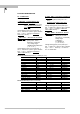
5.14 Characteristic of outputs
P Pulse output
P
100%
Pulses at Q
100%
, full-scale range
Q
F
1 flow direction, or forward flow in
F/R mode
Q
R
Reverse flow in F/R mode
Q
100%
Full-scale range
1 direction of flow
2 directions of flow F/R mode
5
% 100 Max %
0
Q
R
P = 0 Hz Q
F
P
115%
P
100%
P
max
% Max 100 100 Max %
0
Q
R
P = 0 Hz Q
F
115%
P
100%
P
max
P