
Manual


Installation and operating instructions
33
BATCHFLUX
5.10 Entry Code
Fct. 3.4 ENTRY CODE
Press key
→ .
Selection
• NO (no code, press key →
to enter setting mode)
• YES (enter setting mode with key
→
and Code 1:
→ → → ↵ ↵ ↵ ↑ ↑ ↑)
Select with keys
↑ and ↓.
Press key
↵ to return to Fct. 3.4 ENTRY CODE.
5.11 Primary head
Fct. 3.2 FLOWMETER
Press key
→ .
→ DIAMETER = Set the meter size
(see instrument nameplate) press key → .
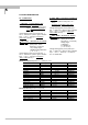
Select size from table of meter sizes:
• BATCHFLUX IFM 5015 K : DN 2,5 - 40
mm equivalent to
1
/
10
- 1
1
/
2
inches
Select with keys ↑ and ↓.
Transfer to subfunction “FULL SCALE“
with key
↵.
→ FULL SCALE = Set the full-scale range,
press key →.
Set as described in Sect. 5.1.
Transfer to subfunction “GKL VALUE
“
with key
↵.
Note: if “VALUE P“ is displayed after
pressing key
↵ .
PULSE/VOL. has been set under Fct. 1.6
PULS.OUTP. P, subfunction “SELECT P“.
Because the full-scale range Q
100%
has been
changed, the output frequency (F) of the pulse
output is over- or undershot:
P
min
= F
min
/ Q
100%
P
max
= F
max
/ Q
100%
Change pulse value accordingly, see Sect. 5.7
Pulse output P, Fct. 1.6.
→ GKL VALUE = Set the primary
constant GK
, press key → .
• 1.0000 - 9.9999 (note information on
instrument nameplate, do not change
setting !)
Change flashing digit (cursor) with keys
↑ and
↓ . Shift cursor 1 place to right or left with keys
→ and ←.
Transfer to subfunction “FLOW DIR.“ with
key ↵.
→ FIELD FREQ. = Magnetic field
frequency, press key → .
• 1/2 (1/2, 1/6 or 1/18 or 50 Hz
or 60 Hz,
• 1/6 see instrument nameplate,
• 1/18 do not change setting !)
The magnetic field frequency is determined by
the program.
Select with keys
↑ and ↓.
Transfer to subfunction “FLOW DIR.“
with
key
↵.
→ FLOW DIR. = Set the direction of flow,
press key → .
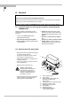
• + DIR.
• - DIR. (for identification of flow
direction see “+“ arrow on primary head, in
F/R mode this identifies the “positive“ flow
direction)
Select with keys
↑ and ↓.
Press key
↵ to return to Fct. 3.2
FLOWMETER.
Zero check: see Fct. 3.3 and Sect. 7.1.
Please refer to Sect. 3.2
“Factory settings“
5