
Manual


Installation and operating instructions 2 BATCHFLUX
Contents
System description 4
Standards and approvals 4
Product liability and warranty 4
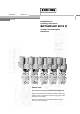
Functional description BATCHFLUX IFM 5015 K 5
Part A System installation and start-up 6 - 16
1 Installation in the pipeline 6 - 11
1.1 Important information 6
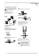
1.2 Suggestions for installation 7
1.3 Installation requirements 8-9
1.3.1 Position of flange 9
1.3.2 Example: centering and sealing the primary head 9
1.3.3 Grounding 9
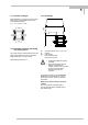
1.4 Installation of the primary head 10
1.4.1 Device description 10
1.4.2 Installation of the IFM 5015 K 10
1.5 Size of connections 11-12
1.5.1 Fastening with tie bolts 11
1.5.2 Fastening with tie bolts (option) 12
2 Electrical connection 13 - 14
2.1 Important information 13
2.2 Attachment plugs 13
2.3 Power supply and outputs 14
3 Start-up 15 - 16
3.1 Checking for availability 15
3.2 Factory settings 16
Part B IFC 015 signal converter 17 - 34
4 Operator control of signal converter with the HHT 010 17 - 27
4.1 Operator control concept 17
4.2 Operating and check elements 18
4.3 Function of keys 18 - 19
4.4 Table of settable functions 20 - 24
4.5 Error messages in measuring mode 25
4.6 Resetting totalizers and deleting error messages, RESET / QUIT menu 26
5 Description of functions 28 - 35
5.1 Full-scale range Q
100%
28
5.2 Time constant 28
5.3 Low-flow cutoff 28
5.4 Display with HHT 010 29
5.5 Internal electronic totalizer 30
5.6 Current output I 30
5.7 Pulse output P 30 - 31
5.8 Status output S (option) 32
5.9 Language 32
5.10 Entry code 33
5.11 Primary head 33
5.12 User-definable unit 34
5.13 F/R mode, forward / reverse flow measurement 35
5.14 Characteristic of outputs 35