
Manual
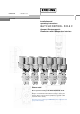


Installation and operating instructions 2 BATCHCONTROL
Contents
System description 4
Standards and approvals 4
Product liability and warranty 4
Functional description BATCHCONTROL IFM 5014C 5
Part A System installation and start-up 6 - 15
1 Installation in the pipeline 6 - 12
1.1 Important information 6
1.2 Suggestions for installation 7
1.3 Installation requirements 8
1.3.1 Position of flange 9
1.3.2 Example: centering and sealing the primary head 9
1.3.3 Grounding 9
1.4 Installation of the primary head 10
1.4.1 Device description 10
1.4.2 Installation of the IFM 5014C 10
1.5 Size of connections 11 - 12
1.5.1 Fastening with tie bolts 11
1.5.2 Fastening with bolts (option) 12
2 Electrical connection 13 - 14
2.1 Important information 13
2.2 Attachment plugs 13
2.3 Power supply and CAN bus 14
2.4 Input and output 14
2.5 Block circuit diagram 14
3 Start-up 15
3.1 Checking for availability 15
3.2 Factory settings 15
Part B IFC 014 batch controller 16 - 20
4 Description of functions 16 - 20
4.1 Contact outputs 16
4.2 Voltage input 16
4.3 Contact input 16
4.4 CAN bus and parameter 16 - 17
4.5 Temperature sensors 17
4.6 Flow sensor 17
4.7 An example for a filling process 17 - 20
Part C Service 21
5 Illustrations of printed circuit boards 21
Part D Technical Data, block diagram and measuring principle 22 - 28
6 Technical data 22 - 26
6.1 Flow during filling and fill volume 22
6.2 Flowmeters 22
6.3 Signal converter 23
6.4 Error limits at reference conditions 24
6.5 Dimensions and weights 25 - 26
6.6 Instrument nameplates 26
7 Block diagram 27