
Manual


11
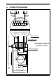
8. CONNECTION DIAGRAM
Flow tube
Hazardous locations
of Zone 1 and 2
E
IFS 4000…-EEx
Primary Head
Intrinsically safe electrode circuits
Increased safe field coil circuit
Coil
I ⊥ I B2 B⊥ B2 1L= 0L=
CURRENT BINARY ADD. POWER
OUTPUT OUTPUTS SUPPLY
TERMINAL COMPARTMENT
ELECTRONICS COMPARTMENT (always "EEx d")
Intrinsically safe ("ib") Increased safe ("e")
electrode circuits field coil circuits
(No. "2", "3", "1") (No. "7", "8")
IFC 040-EEx
Signal Converter
PE
FE
SIGNAL IN-/OUTPUTS 1L= 0L= PE
EQUIPOTENTIAL BONDING CONDUCTOR
≥
4 mm
2
(OPTIONAL)
Flameproof (EEx d) cable
feed-through LC-2/EEx
Field coil wires - green/blue
(PTFE insulated copper)
B
A
E
Coil
Electrode cables - white/pink
(PTFE insulated shielded copper)
Flameproof (EEx d)
terminal feed-through