2/01 Electromagnetic flowmeter in 2-wire technology Addition to the installation and operating instructions ALTOFLUX 2W IFM 4042 K-EEx Compact flowmeter 7.xxxxx.xx.
WARNING ! No changes may be made to the devices. Unauthorized changes might affect the explosion safety of the devices. These additional instructions are an extension to the Installation and Operating Instructions and only applies for the EEx version of the IFM 4042 K electromagnetic compact flowmeter. All technical information described in the Installation and Operating Instructions are applicable, when not specifically excluded or replaced by the instructions in these additional instructions. CONTENTS 1.
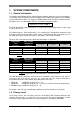
1. SYSTEM COMPONENTS 1.1 General information The Altoflux 2W IFM 4042 K-EEx electromagnetic compact flowmeter in 2-wire technology is in accordance with European Directive 94/9 EG (ATEX 100a) and approved for hazardous classified locations of Zone 1 and 2 by the KEMA conform to the European Standards of the EN 500xx series. The IFM 4042 K-EEx has the following approval number. KEMA 01 ATEX 2200 X The IFM 4042 K-EEx compact flowmeter is designed for ambient temperatures in the range of -40°C up to +60°C.
Meter size Type of protection Increased safety "e" according to EN 50019 Encapsulation "m" according to EN 50028 Electrodes: Intrinsic safety "ib" according to EN 50020 Housing: Flameproof enclosure "d" according to EN 50018 Electrodes: Intrinsic safety "ib" according to EN 50020 Field coils: Increased safety "e" according to EN 50019 Electrodes: Intrinsic safety "ib" according to EN 50020 Field coils: DN10 up to DN20 DN25 up to DN150 DN200 and larger Table 3: Types of protection of primary head.
1.3.3 Cable or conduit entries Dependent on the explosion protection type that the terminal compartment is configured with, (see description on the previous page), can the terminal compartment be equipped with cable entries or conduit adapters. The used cable entries (glands and/or blind plugs) must have a ATEX approval in accordance with the type of protection of the terminal compartment.
Galvanical separation of circuits: • The internal electrode circuit with type of protection "EEx ib" is galvanically connected to the aluminum signal converter housing (i.e. PE potential). • The current output, the additional power supply and the internal field current circuit are galvanically connected to each other. 2.1 Detailed description of the output circuits The terminal compartment of the IFM 4042 K-EEx is, with respect to the explosion protection, available in two versions.
• The current output (terminals I, I⊥ ) and the additional power supply (terminals 1L=, 0L=) must be galvanically separated connected and driven from each other. To avoid voltage or current summation, at least one of the two circuits must be isolated from earth potential. It is not allowed to drive both circuits at the same time with grounded zener barriers. Both current circuits, including all connection cables, must be galvanically separated at all times according to the valid regulations.
Hazardous Area Safe Area IFM 4042 K-EEx (MGM 4042 K-EEx) 4-20 mA 4-20 mA I Process/ Display Unit Transmitter Power Supply (EEx i) I⊥ Vs HTT Figure 2: Connection of IFM 4042 K-EEx in 2-wire mode. The entity parameters of the "EEx i" approved transmitter power supply, including the cable capacitances and inductances, must fit the entity parameters of the IFM 4042 K-EEx compact flowmeter, namely Uo ≤ 30 V, Io ≤ 100 mA.
Figure 3 on the previous page shows an example of the connection of the IFM 4042 K-EEx in 2x2-wire mode. As in the previous example (figure 2), the terminal compartment of the IFM 4042 K-EEx is performed as version A, which means that it is providfed with type of protection "EEx de [ib]". The additional power supply (terminals 1L=, 0L=) of the IFM 4042 K-EEx is supplied by an external power supply unit through a ATEX approved "EEx i" zener barrier with a linear output load.
4.
5. EQUIPOTENTIAL BONDING SYSTEM The IFM 4042 K-EEx electromagnetic compact flowmeter must be incorporated into the equipotential bonding system. Therefore the bonding conductor with a maximum crosssectional area of 4 mm2 (AWG 10) must be connected to the external U-clamp terminal M5 that is press-fitted in the connecting flange at the bottom of the neck of the flameproof signal converter housing. The U-clamp terminal is made of nickel-plated brass to prevent it for corrosion.
8. CONNECTION DIAGRAM SIGNAL IN-/OUTPUTS 1L= 0L= PE A B IFC 040-EEx Signal Converter I⊥ PE FE I B2 B⊥ B2 1L= 0L= CURRENT OUTPUT BINARY ADD. POWER OUTPUTS SUPPLY TERMINAL COMPARTMENT ELECTRONICS COMPARTMENT (always "EEx d") Intrinsically safe ("ib") electrode circuits (No. "2", "3", "1") Increased safe ("e") field coil circuits (No.
9. ORDERING INFORMATION In case of questions about spare or replacing parts contact your local Krohne representative. The part number of the IFC 040-EEx electronics unit is 2.12896.01.00. 10. DATA PLATES Figure 4: Data plate of IFM 4042 K-EEx, type "EEx de [ib]". Figure 5: Data plate of IFM 4042 K-EEx, type "EEx de".
Figure 6: Data plate IFM 4042 K-EEx, type EEx e [ib].
14
11.
16
17