
Owner manual


ALTOFLUX IFM x080 K-EEx and ALTOFLUX IFM x080 K / i-EEx 16
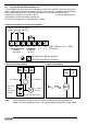
Terminal compartment MODIS version IFC 090i-EEx
Sticker with handling information
for insulating cover plate
Sticker indicating the intrinsically
safe signal in-/output circuits
Insulating cover plate
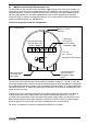
The PE (or FE) conductor must be connected to the press-fitted M5 clamp terminal marked inside
the terminal compartment. This conductor must be guided through the rectangular opening in the
metal dividing plate that separates the non-intrinsically safe power supply terminals from the
intrinsically safe signal in-/output terminals.
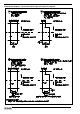
2.6 Connection diagrams MODIS
Sect. 2.3 shows the block diagram of the EEx electromagnetic compact flowmeter. The power
supply (terminals 1L½, 0L½) is connected via cable B. The PE terminal must be connected to the
protective ground conductor of the mains supply.
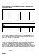
The IFC 090i-EEx electronics unit is provided with intrinsically safe signal in-/output circuits due to
the installed pair of MODIS modules in accordance with the table below.