© KROHNE 07/02 7.02253.21.
WARNING ! No changes regarding safety may be made to the devices. Unauthorized changes might affect the explosion safety of the devices. Be sure to follow these instructions ! IMPORTANT ! • The prescriptions and regulations as well as the electrical data described in the EC-type examination certificate must be obeyed. • Beside the instructions for electrical installations in non-hazardous locations according to the applicable national standard (e.g.
Content 1 1.1 1.2 1.3 1.4 1.4.1 1.4.2 1.5 System components General information ALTOFLUX IFM 4080 / … EEx General information PROFIOFLUX IFM 5080 / … EEx General information VARIFLUX IFM 6080 / … EEx IFC 090 / … -EEx signal converter Electronics compartment Terminal compartment Electronics unit 3 4 6 8 10 10 10 11 2 2.1 2.2 2.3 2.4 2.5 2.
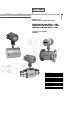
1 System components 1.1 General information ALTOFLUX IFM 4080 / … EEx This meter complies with the European Directive 94/9/EC (ATEX 100a) and approved for hazardous classified locations of Zone 1 and 2 under EC-type Examination Certificate number: KEMA 01 ATEX 2200 X The compact flowmeter is available in two types, namely: IFM 4080 K-EEx regular explosion protected version; IFM 4080 K/i-EEx, MODIS version.
For details see the EC-type Examination Certificate in Sect. 8.1 of these instructions . Primary head The primary head contains two field coils (see table for type of protection) and two electrodes in type of protection intrinsic safety category "ib" according to EN 50020.
1.2 PROFIFLUX IFM 5080 K … EEx The Profiflux IFM 5080 K/…-EEx magnetic-inductive compact flowmeter is in accordance with the European Directive 94/9/EC (ATEX 100a) and approved for hazardous classified locations of Zone 1 and 2 under EC-type Examination Certificate number: KEMA 01 ATEX 2262 X The compact flowmeter is available in two types, namely: • IFM 5080 K-EEx regular explosion protected version; • IFM 5080 K/i-EEx, MODIS version.
Primary head The IFS 5000-EEx primary head of the IFM 5080 K/…-EEx compact flowmeter contains two field coils above and below the measuring tube and two electrodes inside the ceramics measuring tube on both sides. The field coils have type of protection increased safety "e" according to EN 50019 and encapsulation "m" according to EN 50028. The electrodes are provided with type of protection intrinsic safety "ib" according to EN 50020. The primary head is available in meter sizes DN2.5 up to DN100.
1.3 VARIFLUX IFM 6080 K … EEx The Variflux IFM 6080 K/…-EEx magnetic-inductive compact flowmeter is in accordance with the European Directive 94/9/EC (ATEX 100a) and approved for hazardous classified locations of Zone 1 and 2 under EC-type Examination Certificate number: KEMA 02 ATEX 2021 X The compact flowmeter is available in two types, namely: • IFM 6080 K-EEx regular explosion protected version • IFM 6080 K/i-EEx, MODIS version.
Types of protection of primary head Meter size Type of protection Field coils: Increased safety "e" according to EN 50019 Encapsulation "m" according to EN 50028 Electrodes: Intrinsic safety "ib" according to EN 50020 Housing: Flameproof enclosure "d" according to EN 50018 Electrodes: Intrinsic safety "ib" according to EN 50020 DN2.5 up to DN15 DN25 up to DN80 The IFC 090/…-EEx signal converter (described in Sect. 1.4-1.
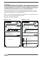
1.4 IFC 090/…-EEx signal converter The IFC 090/…-EEx signal converter consists of a cylindrical housing of die-casted aluminum, which has two separate compartments, divided from each other by an integrated wall with casted flameproof terminal feed-through. The neck at the bottom of the housing contains a flameproof cable feed-through. The signal converter housing is on both ends closed by a cylindrical threaded cover with O-ring sealing.
1.5 Electronics unit This electromagnetic compact flowmeter can be equipped with the regular IFC 090-EEx or with the IFC 090i-EEx electronics unit with intrinsically safe signal outputs (i.e. MODIS version). This version is descripted in the following. Regular IFC090-EEx electronics unit The IFC 090-EEx is used in the regular IFM 4080 K-EEx and can be equipped with one of the following power supplies (depends on the area of application).
2 Electrical connection 2.1 Equipotential bonding system All EEx and EEx/i flowmeters must always be incorporated into the equipotential bonding system of the hazardous area. This connection can be achieved through the PE/FE conductor connected to the PE terminal in the terminal compartment (see figure of terminal arrangement below) or through a separate PE conductor, cross s ectional area at least 4 mm 2, connected to the external PE clamp, placed below the converter housing. 2.
2.3 Connection diagram L L½ SIGNAL IN-/OUTPUTS N L½ PE 100-230 Vac FE 24 Vac/dc A INTRINSICALLY SAFE SIGNAL IN-/OUTPUTS (i.e.
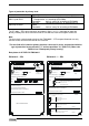
2.4 Regular IFC 090-EEx electronics unit The field cables that enter the terminal compartment of the IFC 090-EEx signal converter unit (i.e. power supply, current and binary outputs) are non-intrinsically safe. To connect external devices to the signal output terminals, the wiring requirements for the type of protection of the IFS x000 … - EEx "d") must be conform to the compartment (standard: increased safety "e", optional: flameproof Primary head international or national standard involved (e.g.
2.5 MODIS version IFC 090i-EEx electronics unit The field cables of the non-intrinsically safe power supply and the intrinsically safe, category "ia" signal outputs enter the terminal compartment of the IFC 090i-EEx signal converter unit via two separate entrances.
Terminal compartment MODIS version IFC 090i-EEx Insulating cover plate Sticker with handling information for insulating cover plate Sticker indicating the intrinsically safe signal in-/output circuits The PE (or FE) conductor must be connected to the press-fitted M5 clamp terminal marked inside the terminal compartment.
Overview of MODIS modules Module Terminal designation P-SA I ⊥, I FA-ST B1, B1⊥ or B2, B2 ⊥ F-PA D, D ⊥ F-FF D, D ⊥ DC-I I+, B1+ Function / Intrinsically safe maximum data Current output (0/4-20 mA), passive Ui = 30 V, Ii = 250 mA, Pi = 1.0 W Ci = 5 nF, L i ≈ 0 Pulse (frequency) output or status in-/output, all passive The function can be set by software Ui = 30 V, Ii = 250 mA, Pi = 1.0 W Ci = 5 nF, L i ≈ 0 Fieldbus module, type Profibus system, passive Ui = 30 V, Ii = 300 mA, Pi = 4.
The active module DC-I is needed in the 24 Vac/dc power supply version to form an active current or pulse output in combination with one of the passive modules P-SA or FA-ST. Due to limited space it is not available for 100...230 Vac supply versions. Possible combinations of the installed MODIS modules for the 24 Vac/dc power supply version of the IFC 090i-EEx IFC 090iEEx version Ex-i1 Ex-i2 Ex-i3 Ex-i4 Ex-i5 Ex-i6 Ex-i7 Ex-i8 Part No. MODIS modules Terminal designation 2.11582.01.00 2.11582.03.00 2.
For the connection diagrams of the intrinsically safe signal in-/outputs of the installed MODIS modules in the IFC 090i-EEx electronics unit (see figure 6, 7 and 8 on the following pages). It has to be noted that the intrinsically safe signal in-/outputs may only be connected to the following listed apparatus' (registering devices like amp-meters, pulse counters, etc.
Connection diagrams 1 to 4 of the intrinsically safe signal in-/outputs ALTOFLUX IFM x080 K-EEx and ALTOFLUX IFM x080 K / i-EEx 20
Connection diagrams 5 to 8 of the intrinsically safe signal in-/outputs ALTOFLUX IFM x080 K-EEx and ALTOFLUX IFM x080 K / i-EEx 21
Connection diagrams 9 to 12 of the intrinsically safe signal in-/outputs ALTOFLUX IFM x080 K-EEx and ALTOFLUX IFM x080 K / i-EEx 22
3 Operation of the signal converter The i-EEx compact flowmeters are always equipped with magnet sensors. In that way it is possible to change the settings of the converter with aid of the magnet-bar without the necessity to open the flameproof converter housing in the hazardous area. For the program functions and settings of the converter the standard Installation and operating instructions have to be consulted.
5 Service See Sect. 5 or contact your (local) KROHNE sales representative for the ordering information of spare parts or replacements of IFC 090…-EEx electronics units and/or power fuses. 5.
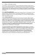
5.2 Replacement of electronics unit Display unit of IFC 090…-EEx A Refer to the standard Installation and Operating Instructions for detailed information about resetting and reprogramming the new electronics unit after replacement. The customer specific data (like the value of the internal totalizer) are stored in DATAPROM IC-18, which must be transferred from the "old" to the "new" electronics unit. See Sect. 8.7 of the standard Installation and Operating Instructions for detailed information.
IFC 090-EEx electronics unit (115/230 Vac version) Copper earth strip Display unit (back side) SE C: Electrode circuit connector (3-pole) B: Field circuit connector (2-pole) Flat cable of display unit D ALTOFLUX IFM x080 K-EEx and ALTOFLUX IFM x080 K / i-EEx D 26
5.3 Replacement of power fuse(s) The power fuse(s) of the different IFC 090…-EEx electronics units (regular or MODIS) have a different rating and are located on slightly different locations on the power supply printed circuit board. Only the power fuse on the 100…230 Vac power supply version of the regular IFC 090EEx electronics unit can be reached without removing the complete unit out of the housing (only the display unit has to be unscrewed). Regular IFC 090-EEx with 24 Vac/dc power supply Note: 1. 2.
Regular IFC 090-EEx with 100…230 Vac power supply Note: 1. 2. 3. Before commencing work, read the instructions in Sect. 5.1 ("Before opening"). Then continue as follows: Remove the cover of the electronics compartment Unscrew the two screws A of the display unit and turn the display unit carefully aside. The fuse-holder, in which the power fuse in accordance with IEC 127-2 size Ø5 x 20 mm is mounted, is now accessible to replace the defect power fuse F1 by a new fuse with the same rating.
MODIS version IFC 090i-EEx Note: 1. 2. 3. 4. 5. 6. Before commencing work, read the instructions in Sect. 5.1 ("Before opening"). Then continue as follows: Remove the cover of the electronics compartment Unscrew the two screws A of the display unit and turn it carefully aside. Disconnect the 2-pole field circuit connector (item B) and the 3-pole electrode circuit connector (item C). See figures in Sect. 5.1 and 5.2 for details.
5.4 Changing power supply voltage This only applies to the regular IFC 090-EEx electronics unit with 100-230 Vac power supply. Note: : 1. 2. 3. 4. 5. 6. 7. Before commencing work, read the instructions in Sect. 5.1 ("Before opening"). Then continue as follows Remove the cover of the electronics compartment. Unscrew the two screws A of the display unit and turn the display unit carefully aside.
6 Ordering information In case of questions about spare or replacing parts contact your local Krohne representative. The part numbers of the several parts are listed in the sections below. 6.1 Regular IFC 090-EEx electronics unit The table below shows the regular (non-MODIS) IFC 090-EEx versions available with the possible power supply units and the accompanying power fuse(s). IFC 090-EEx electronics unit Power supply Part No. 230/240 Vac 2.10664.10.00 115/120 Vac 200 Vac 2.10664.13.00 100 Vac 2.10665.10.
7 Declarations of conformity 7.
7.
7.
8 EC-type examination Certificates 8.
ALTOFLUX IFM x080 K-EEx and ALTOFLUX IFM x080 K / i-EEx 36
ALTOFLUX IFM x080 K-EEx and ALTOFLUX IFM x080 K / i-EEx 37
ALTOFLUX IFM x080 K-EEx and ALTOFLUX IFM x080 K / i-EEx 38
ALTOFLUX IFM x080 K-EEx and ALTOFLUX IFM x080 K / i-EEx 39
ALTOFLUX IFM x080 K-EEx and ALTOFLUX IFM x080 K / i-EEx 40
8.
ALTOFLUX IFM x080 K-EEx and ALTOFLUX IFM x080 K / i-EEx 42
ALTOFLUX IFM x080 K-EEx and ALTOFLUX IFM x080 K / i-EEx 43
ALTOFLUX IFM x080 K-EEx and ALTOFLUX IFM x080 K / i-EEx 44
8.
ALTOFLUX IFM x080 K-EEx and ALTOFLUX IFM x080 K / i-EEx 46
ALTOFLUX IFM x080 K-EEx and ALTOFLUX IFM x080 K / i-EEx 47
ALTOFLUX IFM x080 K-EEx and ALTOFLUX IFM x080 K / i-EEx 48
ALTOFLUX IFM x080 K-EEx and ALTOFLUX IFM x080 K / i-EEx 49
Australia KROHNE Australia Pty Ltd. Unit 19 No. 9, Hudson Ave. Castle Hill 2154, NSW TEL.: +61(0)2-98948711 FAX: +61(0)2-98994855 e-mail: krohne@krohne.com.au Austria KROHNE Ges.m.b.H. Wagramerstr. 81 Donauzentrum A-1220 Wien TEL.: +43(0)1-2 03 45 32 FAX: +43(0)1-2 03 47 78 e-mail: kaut@via.at Belgium KROHNE Belgium N.V. Brusselstraat 320 B-1702 Groot Bijgaarden TEL.: +32(0)2-4 66 00 10 FAX: +32(0)2-4 66 08 00 e-mail: krohne@krohne.be Brazil KROHNE Conaut Controles Automaticos Ltda.