04/02 Magnetic-inductive flowmeters Addition to the installation and operating instructions ALTOFLUX IFM 4080 K-EEx IFM 4080 K/i-EEx Compact flowmeter 7.30917.31.
WARNING ! No changes may be made to the devices. Unauthorized changes might affect the explosion safety of the devices. These additional instructions are an extension to the Installation and Operating Instructions and only applies for the EEx version of the IFM 4080 K or IFM 4080 K / i EEx magnetic-inductive compact flowmeter.
1 SYSTEM COMPONENTS 1.1 General information The Altoflux IFM 4080 K/…-EEx magnetic-inductive compact flowmeter is in accordance with the European Directive 94/9 EC (ATEX 100a) and approved for hazardous classified locations of Zone 1 and 2 by the KEMA conform to the European Standards of the EN 500xx series. The IFM 4080 K/…-EEx has the following approval number.
In case of the MODIS version IFM 4080 K/i-EEx , the electronics unit of type IFC 090i-EEx is provided with protective modules, which provide intrinsically safe output signals of category "ia". The flowmeter is then marked with one of the following codes: • DN25-150: II 2GD EEx d [ia] [ib] IIC T6…T3 (EEx d terminal compartment) or II 2GD EEx de [ia] [ib] IIC T6…T3 (EEx e terminal compartment). • DN200 and up: II 2GD EEx de [ia] [ib] IIC T6…T3.
The terminal compartment (with standard type of protection increased safety "e") is standard equipped with two ATEX approved "EEx e" cable glands. The terminal compartment can also be provided as a flameproof enclosure "d", in which case ATEX approved "EEx d" cable glands of size Pg13.5, Pg16 or M20x1.5 are either factory installed or must be installed by the customer. For flameproof conduit systems, the terminal compartment must have type of protection flameproof enclosure "d" according to EN 50018.
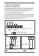
2 ELECTRICAL CONNECTION 2.1 Equipotential bonding system The IFM 4080 K-EEx and IFM 4080 K / i-EEx flowmeters must always be incorporated into the equipotential bonding system of the hazardous area. This connection can be achieved through the PE/FE conductor connected to the PE terminal in the terminal compartment (see figure 1) or through a separate PE conductor, cross sectional area at least 4 mm2, connected to the external PE clamp, placed below the converter housing. 2.
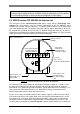
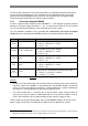
Note: The binary outputs (terminals B1, B⊥ and B2) can only be configured as passive outputs, the current output (terminals I+ and I) can only be configured as active output. 2.3 MODIS version IFC 090i-EEx electronics unit The field cables of the non-intrinsically safe power supply and the intrinsically safe, category "ia" signal outputs enter the terminal compartment of the IFC 090i-EEx signal converter unit via two separate entrances.
See for details figure 5 . Insulating cover plate Sticker with handling information for insulating cover plate Sticker indicating the intrinsically safe signal in-/output circuits Figure 5: Terminal compartment MODIS version IFC 090i-EEx.
The PE (or FE) conductor must be connected to the press-fitted M5 clamp terminal marked inside the terminal compartment. This conductor must be guided through the rectangular opening in the metal dividing plate that separates the non-intrinsically safe power supply terminals from the intrinsically safe signal in-/output terminals. 2.3.1 Connection diagrams MODIS Section 7 shows the block diagram of the IFM 4080 K/ i…-EEx magnetic-inductive compact flowmeter.
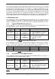
MODIS modul P-SA (passive current output ) FA-ST (frequency/pulse/status output or control input) Nominal values for voltage and current Current: 4 .. 20 mA Working voltage: 8 .. 30V Voltage drop : 8V at 4mA Working voltage: 6 ..
The flameproof terminal feed-through has seven terminals in total, the top two terminals are used for connection of the power supply, the third one is only used for mounting of a metal dividing plate with insulating cover plate. The remaining four are used for the intrinsically safe signal in-/output circuits of the installed MODIS modules. The metal dividing plate and the insulating cover plate warrant the required separation distances (i.e.
Figure 6: Connection diagrams 1 through 4 of the intrinsically safe signal in-/outputs.
Figure 7: Connection diagrams 5 through 8 of the intrinsically safe signal in-/outputs.
Figure 8: Connection diagrams 9 through 12 of the intrinsically safe signal in-/outputs.
3 OPERATION OF THE SIGNAL CONVERTER The IFM 4080 K / i-EEx compact flowmeters are always equipped with magnet sensors. In that way is possible to change the settings of the converter with aid of the magnet-bar without the necessity to open the flameproof converter housing in the hazardous area. For the program functions and settings of the converter the standard Installation and operating instructions have to be consulted.
4.
4.1.1 Replacement of electronics unit Refer to the standard Installation and Operating Instructions for detailed information about resetting and reprogramming the new electronics unit after replacement. The customer specific data (like the value of the internal totalizer) are stored in DATAPROM IC-18, which must be transferred from the "old" to the "new" electronics unit. See Section 8.7 of the standard Installation and Operating Instructions for detailed information.
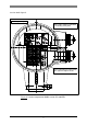
Copper earth strip SE C: Electrode circuit connector (3-pole) B: Field circuit connector (2-pole) Display unit (back side) Flat cable of display unit D D Figure 11: IFC 090-EEx electronics unit (115/230 Vac version). 4.1.2 Replacement of power fuse(s) The power fuse(s) of the different IFC 090…-EEx electronics units (regular or MODIS) have a different rating and are located on slightly different locations on the power supply printed circuit board.
F2 F1 Power fuses F1 and F2 (see detail on the right) Figure 12: IFC 090-EEx electronics unit with 24 Vac/dc power supply. Regular IFC 090-EEx with 100…230 Vac power supply Before commencing work, note the instructions in Section 3.1 ("Before opening") . Then continue as follows: 1. Remove the cover of the electronics compartment. 2. Unscrew the two screws A of the display unit and turn the display unit carefully aside. 3.
Mains transformer 115/230 Vac version Indication of voltage selector (black dot = notch) Sticker with fuse rating SIDE OF DISPLAY UNIT Power fuse F1 (in fuse-holder) Voltage selector Figure 13: Power supply version 115/230 Vac. MODIS version IFC 090i-EEx Before commencing work, note the instructions in Section 3.1 ("Before opening") . Then continue as follows: 1. Remove the cover of the electronics compartment. 2. Unscrew the two screws A of the display unit and turn it carefully aside. 3.
NOTE: The power fuse on the 100…230 Vac version is located on a slightly different position than the fuse of the 24 Vac/dc version ! See location "Fuse_230V". Fuse_230V PTB 97 ATEX 2265 U [EEx ia] IIC PTB 97 ATEX 2265 U Power fuse (24 Vac/dc power supply) Figure 14: IFC 090i-EEx electronics unit (24 Vac/dc version is shown). 4.1.3 Changing power supply voltage This only applies to the regular IFC 090-EEx electronics unit with 100-230 Vac power supply.
5 CONNECTING CABLES NOTE: The below described cables are shown in the connection diagram on the following page. Cable A: Signal cable for current output and binary outputs (pulse and status output). The cable parameters must be in accordance with the regulations in the EN 60079-14 "Electrical installations in hazardous locations" or an equivalent national standard (e.g. DIN VDE 0165).
7 CONNECTION DIAGRAM L L¾ SIGNAL IN-/OUTPUTS N L¾ PE 100-230 Vac FE 24 Vac/dc A INTRINSICALLY SAFE SIGNAL IN-/OUTPUTS (i.e. MODIS) L L½ N L½ A B PE FE 100-230 Vac 24 Vac/dc B IFC 090-EEx Signal Converter B1 B⊥ B2 I+ I BINARY OUTPUTS L N x PE FE x x x CURRENT MAINS OUTPUT SUPPLY Separation plate IFC 090i-EEx Signal Converter ELECTRONICS COMPARTMENT (always "EEx d") (No. "2", "3", "1") Increased safe ("e") field coil circuits OPTION: MODIS (No.
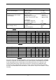
8 ORDERING INFORMATION In case of questions about spare or replacing parts contact your local Krohne representative. The part numbers of the several parts are listed in the sections below. 8.1 Regular IFC 090-EEx electronics unit The below listed table shows the available regular (non-MODIS) IFC 090-EEx versions with the possible power supply units and the accompanying power fuse(s). IFC 090-EEx electronics unit Power supply Part No. 230/240 Vac 2.10664.10.00 115/120 Vac 200 Vac 2.10664.13.
9 DATA PLATES Figure 15: Data plate of IFM 4080 K-EEx. Figure 16: Data plate of IFM 4080 K/i-EEx.
10 DECLARATION OF CONFORMITY 25
11 EC-TYPE EXAMINATION CERTIFICATE 26
27
28
Krohne Altometer Kerkeplaat 12 3313 LC Dordrecht The Netherlands Tel.: ++ 31 (0)78 - 630 63 00 Fax.: ++ 31 (0)78 - 630 63 90 Subject to change without prior notice 730917.31.