
Owner manual


Section 5.6 Part C Technical data, Block diagram and Measuring principle
ALTOFLUX 2W
02/2001
40
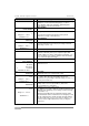
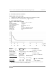
5.6 Limits
PLEASE NOTE !
• The limits specified in the table for process
temperature and operating pressure make
allowance for the tube liner and the flange
standard.
• Abbreviation used:
DIN = DIN 2501 (= BS 4504)
ANSI = ANSI B 16.5
• Refer to certificates of conformity for max.
allowable operating data for hazardous-duty
versions, provided only with hazardous-duty
equipment.
Limits for Teflon
®
PFA liner und Teflon
®
PTFE liner
Liner Flanges Max. operating pressure in bar (psig)
at a process temperature of ...
Standard
Nominal
diameter
Pressure
rating /
Class
≤
40 °C
(≤
105 °F)
≤
60°C
(≤
140 °F)
≤
70 °C
(
≤
158 °F)
≤
90 °C
(≤
195 °F)
≤
100 °C
(≤
210 °F)
≤
120 °C
(≤
250 °F)
≤
140 °C
(≤
284 °F)
1)
PFA
DIN DN 25, 50, 80 PN 40 40
(
580
)
40
(
580
)
40
(
580
)
40
(
580
)
40
(
580
)
40
(
580
)
40 (580)
DN 100, DN 150 PN 16 16
(
232
)
16
(
232
)
16
(
232
)
16
(
232
)
16
(
232
)
16
(
232
)
16 (232)
ANSI 1“, 2“, 3“, 4“, 6“ 150 lb 19.6
(
284
)
19.0
(
275
)
18.7
(
271
)
18.1
(
262
)
17.7
(
256
)
17.0
(
246
)
16.2 (235)
300 lb on request
PTFE
DIN DN 10, DN 15 PN 40 40
(
580
)
40
(
580
)
40
(
580
)
40
(
580
)
40
(
580
)
40
(
580
)
40 (580)
ANSI
3
/
8
“,
1
/
2
" 150 lb 19.6
(
284
)
19.0
(
275
)
18.7
(
271
)
18.1
(
262
)
17.7
(
256
)
17.0
(
246
)
16.2 (235)
300 lb on request
1)
ambient temperature with max. +40 °C / +104 °F
Vacuum load
Liner Nominal diameter Max. operating pressure in mbar (psia)
at a process temperature of ...
DIN ANSI
≤
40 °C
(≤
105 °F)
≤
60 °C
(≤
140 °F)
≤
70 °C
(
≤
158 °F)
≤
90 °C
(≤
195 °F)
≤
100 °C
(≤
210 °F)
≤
120 °C
(≤
250 °F)
≤
140 °C
(≤
284 °F)
PFA
DN 25 - 150 1“- 6“ 0 (0) 0 (0) 0 (0) 0 (0) 0 (0) 0 (0) 0 (0)
PTFE
DN 10, DN 15
3
/
8
“,
1
/
2
“ 0 (0) 0 (0) 0 (0) 0 (0) 0 (0) 500 (7.3) 750 (9.7)
Teflon
®
is a re
g
istered trademark of Du Pont.