
Owner manual


Part C Technical data, Block diagram and Measuring principle Section 5.5
02/2001
ALTOFLUX 2W
39
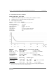
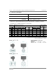
5.5 Dimensions and weights
Flange connections
to
... Dimensions
in mm and (inch)
DIN 2501
DN 10- 150 PN 40, 16 see table
Ansi B 16.5
3
/
8
“- 6“ 150 lb/ RF
≥
300 lb/ RF
see table
dimensions supplied on request
•
Dimension “a“ without flange gaskets (not necessary with Teflon
®
PTFE liner or PFA liner
•
For meter size
3
/
8
“ a flange connection
1
/
2
" is necessary.
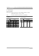
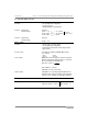
Meter size Dimensions
in mm and (inch)
approx. Weight in
kg (lb)
DIN ANSI
a
(fitting length)
ø D
DN PN inch DIN ISO 13359 ANSI
bc
DIN, ISO ANSI
with DIN
flanges
with ANSI
flanges
10 40
3
/
8
150 (5.91) - 150 (5.91) 330 (12.99) 121 (4.76) 90 (3.54) 88.9 (3.50) 7.5 (17) 8.5 (19)
15 40
1
/
2
150 (5.91) 200 (7.87) 150 (5.91) 330 (12.99) 121 (4.76) 95 (3.74) 88.9 (3.50) 7.5 (17) 8.5 (19)
25 40 1 150 (5.91) 200 (7.87) 150 (5.91) 301 (11.85) 121 (4.76) 115 (4.53) 108 (4.25) 9.5 (21) 11 (25)
50 40 2 200 (7.87) 200 (7.87) 200 (7.87) 383 (15.08) 160 (6.30) 165 (6.50) 152 (6.00) 11 (25) 11 (25)
80 40 3 200 (7.87) 200 (7.87) 200 (7.87) 400 (15.75) 173 (6.81) 200 (7.87) 191 (7.50) 15 (33) 16 (36)
100 16 4 250 (9.84) 250 (9.84) 250 (9.84) 451 (17.76) 233 (9.17) 220 (8.66) 228 (8.98) 18 (40) 21 (46)*
150 16 6 300 (11.81) 300 (11.81) 300 (11.81) 492 (19.37) 257 (10.12) 285 (11.22) 279 (10.98) 25 (55) 21 (46)*
•
max. process pressure ratin
g
acc. DIN flan
g
es, see column “PN“
PN 40 = 580 psi
g
and PN 16 = 232 psi
g
DN 10 – 40 /
3
/
8
“ - 1
1
/
2
"
Tolerance details
for fitting length
dimensions “a“
Standard min ± 1mm / ± 0.04“
ISO DIN 13 359 +0 / -3 mm / +0 / -0.12“
DN 50 – 150 / 2“ – 6“