
Owner manual

02/2001
ALTOFLUX 2W
3
&RQWHQWV
•
Your operatig data 2
•
System description 4
•
Product liability and warranty 4
•
CE / EMC / Standards / Approvals 4
•
Software history 4
7HLO$ ,QVWDOODWLRQDQG6WDUWXS
1 Installation 5 - 10
1.1 Items included with supply 5
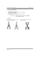
1.2 Handling 5
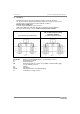
1.3 Installation location 6
1.4 Suggestions for installation 7
1,5 Installation in the pipeline 8
1.6 Torques 9
1.7 Grounding 10
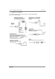
2 Electrical connection 11 – 16
2.1 Information on electrical connection and connection data 11
2.2 Output circuit diagrams 12 – 13
2.3 Characteristic of the outputs 14 – 16
3 Start-up 17
3.1 Power ON and measurement 17
3.2 Factory settings 17
7HLO% ,)&6LJQDOFRQYHUWHU ²
4 Operation of the signal converter 18 - 33
4.1 KROHNE operator control concept 18
4.2 Operating and check elements 19
4.3 Function of keys 20 – 21
4.4 Table of settable function 22 – 32
4.5 Error messages in measuring mode 33
4.6 Reset counter and cancel error messages 33
7HLO& 7HFKQLFDO'DWD%ORFNGLDJUDPXQG0HDVXULQJSULQFLSOH ²
5 Technical Data 34 - 40
5.1 Full-scale ranges 34
5.2 Error limits at reference conditions 35
5.3 IFC 040 Signal converter 36 – 37
5.4 IFS 4002 Primary head 38
5.5 Dimensions and weights 39
5.6 Limits 40
6 Block diagram of signal converter 41
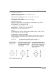
7 Measuring principle 42
8 If you need to return flowmeters for testing or repair to KROHNE 43