M R MASTER REFERENCE O R W N E ’ S R E S SUBWOOFER F E R E N C E
Master Reference Subwoofer Owner’s Reference, v00.1 Krell Industries, Inc. 45 Connair Road Orange, CT 06477-3650 USA TEL 203-799-9954 FAX 203-891-2028 E-MAIL krell@krellonline.com WEBSITE http://www.krellonline.com This product complies with the EMC directive (89/336/EEC) and the low-voltage directive (73/23/EEC). WARNINGS Do not place flammable material above or beneath the subwoofer. Before making connections to the subwoofer, ensure that the back panel power switch is in the down position.
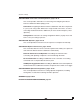
Overview This owner’s reference is written to assist you with the seamless integration of the Master Reference Subwoofer into your audio/video system. Due to the size and weight of the subwoofer, there are special placement and installation issues that require your attention. In addition, to use the programmable electronic crossover, you need to set system configurations before you play music.
(Overview continued) SECTION FOUR: Connections and Configurations, pages 30- 41 This section provides information on connecting and configuring the Master Reference Subwoofer before playing music. Connections. Integrating the Master Reference Subwoofer with other components in your system using CAST, balanced, or single-ended connections, as well as connecting the Master Reference Subwoofer (for stereo and low frequency effect operation). Configurations.
List of Illustrations Figure 1, page 16 Master Reference Subwoofer Placement Options Figure 2, page 18 Master Reference Subwoofer Front Panel Figure 3, page 20 Master Reference Subwoofer Back Panel (Power) Figure 4, page 21 Master Reference Subwoofer Back Panel (Inputs and Outputs) Figure 5, page 25 Master Reference Subwoofer Remote Control v
A Letter from Dan D’Agostino Dear Audio Enthusiast, Thank you for your purchase of the Master Reference Subwoofer. The Master Reference Subwoofer is the result of my ongoing quest for designing reference caliber audio components. I have been designing audio amplifiers for high performance audio systems for more than thirty years. The Master Reference Subwoofer represents the culmination of many years of engineering research and discerning listening.
SECTION ONE About Krell This section describes the Krell Legacy, Krell’s revolutionary CAST technology, and defines key terms used in this reference. The Krell Legacy “I design every Krell component to set the standard for workmanship, style, and performance.” Dan D’Agostino High-end audio is a demanding pursuit—an ongoing quest for excellence in music reproduction that drives equipment manufacturers to strive for the absolute in design and performance.
From the first Krell product — the KSA-100 — to the present, Dan D’Agostino has continually “pushed the envelope” of performance in his search for greater amplifier power and now, subwoofer power. His exploration of technologies, driven by his never-ending quest to elevate the standard of excellence, has resulted in breakthrough audio designs.
(SECTION ONE: About Krell continued) Revolutionary Krell CAST Technology The Master Reference Subwoofer is designed with Current Audio Signal Transmission circuit technology, termed CAST. This circuitry is a revolutionary method of connecting analog audio components for unparalleled sonic performance.
CAST and Krell Current Mode Combined CAST technology combined with Krell Current Mode circuitry take signal transmission to the next evolutionary level. Krell Current Mode is the technology developed to transfer the musical signal within a component, used in Krell components since 1995. Krell has now added CAST technology, a new method of transferring the musical signal between components.
(SECTION ONE: About Krell continued) Ensuring Maximum Performance The function of the Master Reference Subwoofer is to reproduce, with unprecedented authority and fidelity, the lowest reaches of the audio spectrum, thereby extending the low frequency capabilities of even the finest music and home theater systems. The Krell Master Reference Subwoofer sets a new standard in powered subwoofer design. At the heart of the Master Reference Subwoofer is its proprietary interface.
Active Motion Control is a unique circuit topology developed by Krell specifically for the Master Reference Subwoofer. An instrument grade accelerator, mounted to one of the drivers, relays information about the driver’s position to the Active Motion Control circuit, where it is compared to the musical waveform at the amplifier input stage. Amplifier parameters are then adjusted to ensure that driver motion is faithful to the input signal, and feedback is precisely applied to preserve sonic impact.
(SECTION ONE: About Krell continued) (Drivers continued) Two 80 oz. strontium ferrite magnets are affixed to the custom-made, cast magnesium speaker frame. The magnet assembly has been contoured to produce a powerful, focused, magnetic field. A robust, doped (reinforced) paper cone, chosen for its high strength and low weight, is affixed at one end to the speaker frame via a special rubber surround. This surround has a unique geometry that resists cavitating (turning inside out) under high pressures.
Totally Balanced Operation Balanced circuits ensure optimum signal to noise ratios, signal preservation, and accuracy of delivery under every condition; however, the primary benefit of balanced circuitry is loudspeaker control. The Master Reference Subwoofer finesses the low frequency range with totally balanced operation from input to output, employing CAST or XLR inputs.
(SECTION ONE: About Krell continued) (Totally Balanced Operation continued) The Output Stage. In the output stage of a conventional amplifier, loudspeaker control is accomplished by driving the positive speaker terminal only. Each Master Reference Subwoofer uses two Krell Current Mode circuit paths, one to drive the positive and one to drive the negative terminals of the loudspeakers.
(SECTION ONE: About Krell continued) Definition of Terms Following are the definitions of key terms used in your owner’s reference manual. Configurations Krell Link A method of configuring multiple Krell preamplifiers, amplifiers, and associated components and synchronizing their stand-by/ operational modes. Using Krell Link in/out connections and MIDI cables, the remote capabilities of the linked components are controlled by one component, called the control component.
(SECTION ONE: About Krell continued) (Definition of Terms continued) Krell CAST Current Audio Signal Transmission (CAST) is a proprietary Krell circuit technology for connecting analog components, in which the audio waveform is transmitted between components in the current rather than the voltage domain. The speed and bandwidth that CAST provides yield astounding levels of accuracy and realism. Krell components connected via CAST perform as if they are all part of a single circuit.
Krell Current Mode A proprietary Krell circuit topology in which the audio gain stages operate in the current domain. Krell Current Mode provides speed and bandwidth performance that is not possible with less sophisticated voltage designs. Programmable Electronic Crossover A proprietary full-function crossover designed for the Master Reference Subwoofer. The crossover is comprised of two sections: the high-pass filter and the low-pass, or sub, filter.
SECTION TWO Unpacking and Placement This section describes the procedures for safely unpacking and placing the Master Reference Subwoofer. Unpacking Each Master Reference Subwoofer shipping crate measures 26 in. (66 cm) wide x 32 in. (81.3 cm) high x 35 in. (88.9 cm) deep and contains one Master Reference Subwoofer. The combined weight of the crate and subwoofer is 494 lb. (224.5 kg). Each Master Reference Subwoofer is 18.8 in. (47.8 cm) wide x 20.1 in. (51.1 cm) high x 28.5 in. (72.
In the packing crate you will find: 1 Master Reference Subwoofer In the space underneath the subwoofer, you will find: 1 power cord 1 remote control 2 AAA-size 1.5 volt batteries for the remote control 1 T-10 Torx wrench for the remote control To Remove the Subwoofer from the Packing Crate: 1. Remove all accessories from the packing crate. 1 person needed 2. Lift the subwoofer off the crate base and gently place it on the floor. Set the crate base aside. 4 people needed 3.
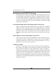
(SECTION TWO: Unpacking and Placement continued) Figure 1 Master Reference Subwoofer Placement Options Scenario 1: Stereo 3 1 2 1 Left Loudspeaker 2 Right Loudspeaker 3 Master Reference Subwoofer 4 Optimum Listening Position 4 Scenario 2: Home Theater, Rear Projection 1 Left Front Loudspeaker 2 Center Speaker 3 Master Reference Subwoofer 4 Right Front Loudspeaker 5 Rear Projection TV 6 Left Rear Loudspeaker 7 Right Rear Loudspeaker 8 Optimum Listening Position 3 2 5 1 4 8 6 7 Scenario 3: Home
Placement Before you install the Master Reference Subwoofer, review the following guidelines to choose the location for the subwoofer. This facilitates a clean, trouble-free installation. Make sure the Master Reference Subwoofer, in addition to other items (amplifiers, other system components, furniture) in the listening room, does not exceed the listening room’s maximum floor load.
SECTION THREE Features This section provides illustrations of the Master Reference Subwoofer front panel, back panel, and remote control, and descriptions of front panel, back panel, and remote control features. Front Panel Description See Figure 2. The Master Reference Subwoofer front panel provides power on and subwoofer status displays. Front panel features and their descriptions follow.
1 Power Button Use this button to switch the Master Reference Subwoofer from the stand-by to the operational mode. 2 Power LED The blue power LED illuminates when the Master Reference Subwoofer is in the operational mode and flashes when any remote control key is pressed. 3 Stand-by LED The red stand-by LED illuminates when the back panel power switch is in the up position and the Master Reference Subwoofer is in the stand-by mode.
(SECTION THREE: Features continued) Figure 3 Master Reference Subwoofer Back Panel (Power) 76 Figure 3 Power 6 Power Switch 7 AC Input Specification 8 IEC Power Connector Figure 4 Back Panel Remote Connections 9 Krell Link In and Out 10 12 VDC In and Out 11 12 VDC LFE In 12 RC-5 In 13 RS-232 50/60 Hz Inputs 14 Left and Right CAST Inputs 15 Left and Right Balanced Inputs 16 Left and Right Single-ended Inputs 17 LFE CAST Input 18 LFE Balanced Input 19 LFE Single-ended Input KRELL INDUSTRIES, INC.
Figure 4 Master Reference Subwoofer Back Panel (Inputs and Outputs) 9 11 12 13 10 IN LINK RC-5 12VDC KRELL OUT IN OUT LFE IN IN RS-232 14 17 16 INPUT LEFT 19 INPUT LFE INPUT RIGHT 18 15 20 22 HIGH-PASS HIGH-PASS OUTPUT OUTPUT LEFT RIGHT BY-PASS BY-PASS OUTPUT OUTPUT LEFT RIGHT 21 23 25 Master Reference Subwoofer 24 NO USER SERVICEABLE PARTS INSIDE CAST PAT.
(SECTION THREE: Features continued) Back Panel Description See Figures 3 and 4. The Master Reference Subwoofer back panel provides input and output connections, remote connections, and power. Back panel features and their descriptions follow. Power 6 Power Switch Use this switch to power the Master Reference Subwoofer from off to the stand-by mode. 7 AC Input Specification The Master Reference Subwoofer is designed to be used with 50/60 Hz power lines only.
12 RC-5 In The Master Reference Subwoofer is equipped with an RC-5 input that makes custom installation easy and secure by accepting baseband RC-5 input commands from hardwired remote controllers. The RC-5 input can be used, for example, when the subwoofer’s IR sensor (5) is obscured from direct view. 13 RS-232 The Master Reference Subwoofer is equipped with an RS-232 port, which receives messages from a computer-based control system, providing integrated control of all subwoofer functions.
(SECTION THREE: Features continued) (Inputs continued) 19 LFE Single-ended Input The Master Reference Subwoofer is equipped with a low frequency effect ( LFE ) single-ended input. This input is connected to a surround preamp/processor, for use with Dolby 5.1 and DTS encoded software.
Figure 5 Master Reference Subwoofer Remote Control CAST PHASE POWER 28 27 26 PRESET 1 29 2 3 THTR 4 SAVE 31 30 Power 26 Power Key UNIT 1 2 3 4 32 Operation Keys 27 CAST Key 28 Phase Key 29 Preset Key 30 Thtr (Theater) Key 31 Save Key 32 Unit Key 33 All Key 34 Mute Key ALL MUTE 34 33 SECTION SUB 35 36 HIGH MENU ENTER 38 37 PARAMETER TYPE SLOPE FREQ 39 40 ADJUST Filter Selection Keys 35 Section Sub Key 36 Section High Key LEVEL 42 41 43 Menu Keys 37 Menu Key 38 Enter Key Filte
(SECTION THREE: Features continued) Remote Control Description Battery Installation and Removal The Master Reference Subwoofer control uses two AAA-size 1.5 Volt batteries. Batteries are included with the shipment. To install the batteries: 1. Remove the backplate, using the supplied T-10 Torx wrench. 2. Install the batteries, following the battery position diagram on the plastic battery receptacle. 3. Replace and secure the backplate. The remote control is ready for operation.
Remote Control Functions See Figure 5. The Master Reference Subwoofer remote control provides power, subwoofer functions, and menu and programming options, as well as stand-by and operational mode commands for components connected through Krell Link. Remote control features and their descriptions follow. Power 26 Power Key Use this key to switch the Master Reference Subwoofer from the stand-by to the operational mode. Operation Keys 27 CAST Key Use this key to select CAST operation for an available input.
(SECTION THREE: Features continued) (Operation Keys continued) 32 Unit Keys Use these keys to assign an ID to each component when multiple subwoofers are installed in a configuration. For instructions on assigning an ID, see Optional Configurations, on page 48, for more information. 33 All Key Use this key to control all subwoofers at once, for example, to mute, power on, or set preset configurations for all subwoofers in a configuration.
Filter Parameter Keys 39 Type Key Use this key to select the filter profile desired. The front panel display (4) shows the current selection. See Step III. Configure the Programmable Electronic Crossover, on page 36, for filter options and instructions. 40 Slope Key Use this key to adjust the slope of the high-pass or low-pass filter. The front panel display (4) shows the selected setting. See Step III. Configure the Programmable Electronic Crossover, on page 36, for slope adjustment instructions.
SECTION FOUR Connections and Configurations See Figures 3 and 4. Overview This page outlines the connections (Steps I and II ) and configurations ( Steps III through VI ) for the Master Reference Subwoofer. These instructions let you set up your subwoofer for optimum performance. Detailed instructions begin on page 31. Krell recommends that you configure your Master Reference Subwoofer in the following order. Step I.
Connections and Configurations The remote control is the main input device for the Master Reference Subwoofer. All initial setup and subsequent system configuration adjustments must be made through the remote control or via the RS-232 port.
(SECTION FOUR: Connections and Configurations continued) Switching Between CAST and Balanced Inputs The Master Reference Subwoofer offers a number of user-controlled options for choosing inputs and for switching from one input to another, using the remote control in conjunction with the menu option. See B. To Activate CAST Inputs, on page 34 for more information.
3. Connect the cables from the left and right Krell CAST 4-pin inputs (14) on the back panel to the left and right main preamplifier or processor outputs. For balanced or single-ended operation, connect the interconnect cables from either the left and right balanced (15) or the single-ended inputs (16) on the Master Reference Subwoofer back panel to your left and right preamplifier or processor outputs. 4.
(SECTION FOUR: Connections and Configurations continued) (Step II. Connecting the Master Reference Subwoofer to Your System continued) 7. Plug the AC power cord into the IEC connector on the subwoofer back panel. Plug the other end into the AC outlet. IMPORTANT The CAST and LFE inputs must be enabled through the menu to be operational. To activate the low frequency effect (LFE), see Choosing Stereo, LFE, or Stereo/LFE, below. B. To Activate CAST Inputs Use the menu to select which CAST inputs to enable.
C. Choosing Stereo, LFE, or Stereo/LFE Your Master Reference Subwoofer can operate in stereo mode, low frequency effect (LFE) mode, or stereo/LFE mode. For optimum subwoofer performance, Krell recommends using the stereo/LFE combination. The connections and configurations described above in Connecting the Master Reference Subwoofer to Your System and Configuring the Programmable Electronic Crossover connect and configure your subwoofer to operate in stereo mode.
(SECTION FOUR: Connections and Configurations continued) Step III. Configure the Programmable Electronic Crossover This section explains how to configure the subwoofer’s two sections, the low-pass (sub) and high-pass filters, by selecting the appropriate filter profile (Butterworth, Bessel, or Linkwitz-Riley), and adjusting the slope, frequency, and level parameters for each filter profile. Configuring the programmable electronic crossover is required for stereo and stereo/LFE operation.
3. Low-pass Filter Level a. Press the level key (42). b. Use the adjust keys (43) to select the desired level setting (in 1 dB increments). Level range is ± 6 dB. Note See Step IV. Match the High-pass and Low-pass Filter Levels, on page 38, for more information on level matching. D. Select the High-pass Filter Press the section high key (36) on the remote control to select the high-pass filter. The front panel display (4) shows HIGH ADJ. E.
(SECTION FOUR: Connections and Configurations continued) Step IV. Match the High-pass and Low-pass Filter Levels This section explains how, once the programmable electronic crossover has been configured, to match the high-pass and low-pass filter levels using the Master Reference Subwoofer’s built-in noise generator. Step A describes muting the low-pass filter while adjusting the high-pass flter level. Step B describes muting the high-pass filter while adjusting the low-pass filter level.
Notes You can switch the low-pass filter on and off using the mute key, to help compare the filter levels. Every time you adjust the level, the front panel display shows the numeric value of the level. After three seconds of inactivity, the screen becomes blank. You have adjusted the high-pass filter. You can also use a sound pressure level meter for this process; however, it is not required. B. Adjust the Low-pass Filter 1. Press the menu key (37). 2. Press the up adjust key (43) to select MUTE. 3.
(SECTION FOUR: Connections and Configurations continued) C. To End Noise Generation 1. Press the menu key (37) to select the main menu. 2. Press the up adjust key (43) to select NOISEGEN. 3. Press the enter key (38), then press the up adjust key to select NOISE OFF. 4. Press the enter key to end noise generation and return to the main menu. 5. Press the menu key to exit the menu mode. Step V.
To save a setting configuration to a preset: 1. Press the save key (31). 2. Press the preset number to which the settings will be assigned. The front panel display (4) shows SAVING then SAVED. Note If you press save then decide you do not wish to save, press the save key again before pressing the preset key. Recalling Presets 1. Press the preset key (29, 30). 2. The preset number appears in the front panel display (4).
SECTION FIVE Operation This section explains how to manually power on your system and subwoofer for operation and explains the importance of powering on in the appropriate order. After the subwoofer is connected with your system, you can power on the subwoofer for operation. The order in which you power on your system is critical.
If You Wish to Turn Your System Off: Turn your system off if it will not be used for a long period of time. It is critical that you turn off your system in the following order. 1. Press the power button (1) to return the Master Reference Subwoofer to the stand-by mode. The red stand-by LED illuminates (2). 2. Move the power switch (6) on the back panel to the down (off) position. 3. Turn off the amplifiers. 4. Turn off the preamplifier(s) and surround processor. 5. Turn off the source components.
SECTION SIX Optional Connections This section describes three optional connections for the Master Reference Subwoofer. Krell Link connections (9) allow you to synchronize subwoofer operation with other Krell components that have Krell Link in and out connectors. The RS-232 port (13) allows you to connect the subwoofer to a computer-based control system. The 12 VDC (12 V trigger) input and output (10) allow you to integrate the subwoofer into a system with other components that use a 12 Volt trigger.
3. Connect one end of a MIDI cable to the Krell Link out connector, on the control component back panel. 4. Connect the other end of a MIDI cable to the Krell Link in connector, on the back panel of the next component. 5. To link another component, connect another MIDI cable to the Krell Link out connector on the back panel of the second component. Connect the remaining end of the MIDI cable to the Krell Link in connector, on the back panel of a third component. 6. Link additional components, if desired.
(SECTION SIX: Optional Connections continued) RS-232 The RS-232 port (13) allows you to send operational instructions directly into the Master Reference Subwoofer from a computer-based control system, providing integrated control of all subwoofer functions. This feature also allows the Master Reference Subwoofer to report operational status, through the RS-232 status feedback system.
SECTION SEVEN Optional Configurations Five optional configurations are available on the Master Reference Subwoofer, to further customize subwoofer operation. Instructions for optional configurations follow. AC Mains Menu This option allows the Master Reference Subwoofer to be powered on from an AC wall receptacle with a dedicated switch, rather than from the back panel switch or other remote option. 1. Press the menu key (37). 2. Use the adjust keys (43) to select the AC Mains menu.
(SECTION SEVEN: Optional Configurations continued) Mute Menu This option allows you to customize the mute key to mute all subwoofer outputs or only selected outputs. Also see Step IV. Match the High-pass and Low-pass Filter Levels, on page 38, for more information on mute key configuration. 1. Press the menu key (37). 2. Use the adjust keys (43) to select the mute menu. The front panel display (4) shows MUTE. 3. Press the enter key (38). The front panel display shows LPF ONLY. 4.
Exit Menu This option allows you to exit the menu mode. 1. Press the menu key (37) or use the adjust keys (43) to select the exit menu. The front panel display (4) shows EXIT. 2. Press the enter key (38). You exit the menu mode.
Warranty Each Krell Master Reference Subwoofer has a limited warranty of five years for parts and labor on circuitry, for all sections except the loudspeaker driver assemblies. The loudspeaker driver assemblies have a warranty of one year, for defects due to manufacture only. Should this product fail to perform at any time during the warranty, Krell will repair it at no cost to the owner, except as set forth in this warranty. This warranty does not apply to damage caused by acts of God or nature.
Krell is not responsible for any damage incurred in transit. Krell will file claims for damages as necessary for units damaged in transit to the factory. You are responsible for filing claims for shipping damages during the return shipment. Krell does not supply replacement parts and/or products to the owner of the unit.
Return Authorization Procedure If you believe there is a problem with your component, please contact your dealer, distributor, or the Krell factory to discuss the problem before you return the component for repair. To expedite service, you may wish to complete and e-mail the Service Request Form in the Service Section of our website at: http://www.krellonline.com To contact the Krell Service Department TEL 203-799-9954, Monday-Friday 9:00 am to 5:00 PM EST FAX 203-799-9796 E-MAIL service@krellonline.