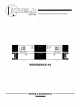
DIGITAL C==:D0 ....
INTRODUCTION Thank you for your purchase of the Krell REFERENCE64 Digital-to-Analog Processor and welcome to the Krell family of audio components. Krell is dedicated to the development of technologically advanced components for the reproduction of digitally recorded music. The REFERENCE64 redefines excellence in the Krell tradition of uncompromising performance through leading-edge technology.
INTRODUCTION This Owner’s Reference is designed to ensure the clear, trouble free installation of your REFERENCE64 processor. Basic Installation, Operation and Quea{ion and Answer sections are provided. Should you have any questions or comments, please feel free to contact your authorized dealer or the KRELLstaff for assistance.
TABLE OF CONTENTS 5 UNPACKING INSTRUCTIONS 6 ASSEMBLY INSTRUCTIONS 8 PLACEMENT 9 AC POWER CONSIDERATIONS 10 INPUT 19 PROCESSOR OPERATION 21 OPERATING INSTRUCTIONS 23 QUESTIONS AND ANSWERS 26 27 AND OUTPUT CONNECTIONS SPECIFICATIONS WARRANTY AND SERVICE INFORMATION PAGE4
UNPACKING 1. Open the box and remove the top layer items will now be visible: 1 1 1 1 1 1 of foam. The following REFERENCE 64 D/A PrOcessor REFERENCE 64 Power Supply Power Coupler AC power cord AT&Tcable (1 mtr) Packet containing the Owner’s Reference Card NOTE: If any of these items are not included, authorized dealer immediately for assistance. and Warranty please contact your 2. Carefully remove the Processor, Power Supply and accessories from the box.
ASSEMBLY ASSEMBLY INSTRUCTIONS 1. The processor is designed to sit directly on top of its companion Power Supply. There is a mechanical interlock built into the front feet of the processor and the chassis cover of the Power Supply. The units are secured together in the rear by the power coupler. 2. Place the Power Supply on a clear work surface. Notice the locking shoes at the front top of the Power Supply cover and the lock pins at the rear top of the Power Supply cover. 3. Locate the Processor main unit.
ASSEMBLY 5. Locate the Processor/ Power Supply coupler assembly. This assembly can only be installed in one direction. The wider portion of the assembly with the mal~ connectors goes into the female connectors inthe center of the Power Supply. The female connectors on the power coupler go into the Processor’s male connectors. Once the coupler has been firmly pressed into place; secure it, utilizing the four thumb screws provided.
PLACEMENT PLACEMENT Before you install the REFERENCE 64 into your system, recommend that you follow these guidelines in choosing location. This will facilitate a clean, trouble-free installation. we the 1. Although well shielded, the Processor should not be placed in close proximity to hum-sensitive components (ioe. preamps, turntables, tuners, etc.) that can create interference and induce hum. 2.
AC POWER AC POWER CONSIDERATIONS NOTE: While the REFERENCE64 has superb regulation and does not require a dedicated AC Circuit, we strongly advise against connections through extension cords or multiple AC adaptors. High quality 15 amp grounded AC strips are acceptable. High quality AC line conditioners or filters can be utilized if they are grounded and meet or exceed the unit’s Power Supply rating of 300VA. CAUTION: Do not remove or bypass the ground pin on the end of the AC cord.
CONNECTIONS INPUT AND OUTPUT CONNECTIONS CAUTION: When making connections other, make sure the power amplifier is in the MUTEor STANDBYmode. to this component or any is OFF and the preamplifier 1. Connect the AC Mains cord to the back of the REFERENCE64 Power Supply and plug the power cord into th AC Mains. CAUTION:Only plug the Power Supply into the AC Mains after the power coupler joining the processor and Power Supply has been installed and secured.
CONNECTIONS 2. Connect the REFERENCE64 analog input of your preamplifier. output to the line level The REFERENCE64 is equipped with two analog output configurations" Single-ended via RCA connectors and Balanced via XLR connectors. If your preamplifier has high level balanced inputs, we recommend the balanced outputs of the Processor be used. There are considerable sonic benefits associated with the use of balanced interconnection.
CONNECTIONS 3. The Left and Right channel RCA outputs are labeled on the back panel. The balanced outputs are not labeled. The balanced connector closest to the Left RCAoutput is the left channel output and the connector closest to the RCAright output is the right balanced output. Care should be taken to insure that the channel orientation between the Processor and the high level inputs of your preamplifier is maintained. 4.
CONNECTIONS Typical System Diagram. Connection LOUDSPEAKERS Digital components can connect to different inputs than are shown.
CONNECTIONS - TAPE MONITOR INPUTS 1 Digital 2 Digital AND OUTPUTS only tape output: Intended for CD-R or DAT monitor inputs using auto selection system 1 AT&Tnormally active, priority over coax input 1 coax selected by default system The digital signal at the tape output is the active digital input signal selected. The use of external clock or TimeSync feature does not interfere with the output of the selected digital signal to the tape output RCA.
CONNECTIONS DIGITAL SOURCE TO D/A CONVERTER INTERLINK CONSIDERATIONS Care should be taken in selectihg the type of cable used to link the digital source to your Processor, We suggest the AT&Twide-band width fiber optic cable be used. The AT&Tformat has a bandwidth of approximately 50 MegaBit. This allows accurate transmission of the digital bit stream without data corruption and proves to be sonically superior.
’"’’",’ CONNECTIONS TIMESYNC TimeSync is a proprietary interlink system that enables a Krell CD transport and REFERENCE 64 to link and run on the CD transport clock. The TimeSync system can only be had on specific Krell transports. The DT- 10 and MD- 10 CD Transports come standard with the TimeSync output. The MD-20 can have the TimeSync installed as a new or additional purchase option. The TimeSync input allows the clock of selected Krell transports to become the system clock.
CONNECTIONS The operation of the Processor utilizing the TimeSync feature requires that the data input be selected first and then the The TimeSync and the DATAinput TimeSync input be selected. selected must be from the same source. If the DATAand TimeSync are from different sources the processor will, after a very short period, go into a MUTEmode.
CONNECTIONS HOW TO CONNECT AT&T CABLES: a. Remove the plastic cover from the outside of the AT&T transmitter (located on Transport) and receiver (located on Processor). b. Locate the slot on the top of the AT&Treceptacle. c. Locate the key on the top of the AT&Tcable. d. Remove the plastic cap from both ends of the AT&Tcable. e. Slide the cable connector into the AT&Treceptacle sliding into the designated slot. with the key f.
OPERATION INPUT SELECT SWITCHING The REFERENCE64 has multiple digital inputs. Each input has its own input switch and direct path to the digital Processor. When an input is selected, the corresponding LED will illuminate. ST XLR TOSH/C1 AT&Tfiber optic input Balanced AES/EBU digital input Toshiba fiber optic input (Priority) and Coaxial input Coaxial input COAX 2 INPUT FREQUENCY INDICATORS When the input signal locks with the Processor, the corresponding input frequency LED will illuminate.
OPERATION SOURCE AND MONITOR SELECTION The SOURCEbutton directs the signal from the Processor input selection section to the DACand analog output stage. The source button must be depressed to listen to the selected input through the main audio system. The MONITOR button routes the output of the component connected to the digital tape loop input to the DACand analog output stage. This enables you to listen to the digital tape recorder output while recording.
OPERATION OPERATING INSTRUCTIONS 1. Select an input with the Input switch. Notice the Signal LED will illuminate when the digital ~ource is turned on and has linked with the Processor. Once this link is complete, the Processor is ready to pass a signal. If you are utilizing the TimeSync interlink, press the TimeSync button at this time. The TimeSync LED will illuminate. 2. Be sure that your preamplifier’s volume control completely to the OFF (lowest volume) position. is turned 3.
OPERATION NOTE: While your REFERENCE64 will perform beautifully from the moment you turn it on, it requires a minimum warm-up period of 8 hours before it begins to show its strongest sonic qualities. It will continue to improve over time. Discrete components are utilized in the analog output stage and the warm-up period allows them to reach thermal equilibrium. Your installation is now complete.
QUESTIONS AND ANSWERS Q. My CD player has both fiber one should I use? optic and coaxial outputs. Which A. Given a choice, we prefer the’AT&Toptical link due to its ability to completely isolate the grounds between the digital source component and the Processor. This minimizes the possibility of ground loops in the digital components. The AT&Tformat also has the added benefit of substantially higher bandwidth than coax or the standard fiber optic interface.
QUESTIONS Q. I am not getting be wrong? AND ANSWERS any sound through the Processor. What could A. Most likely there has been a simple mistake in installation. Check all connections IN and OUTof the Processor. Is the digital source component powered? Check all power connections. Have you selected the correct source on your preamp? Check the front panel LED’s for Power Supply stability. If you still have no sound, turn off the power and contact your dealer. Q.
QUESTIONS AND ANSWERS Q. While listening periods of silence tioning? to my REFERENCE64 1 experience occasional through my speakers. Is my Processor malfunc- A. Drop outs are caused by two primary reasons. First, drop outs can be caused by data corruption. Corruption in the data may be due to a poor input connection, damaged or dirty source material, or interconnects which do not have enough bandwidth.
SPECIFICATIONS FREQUENCY RESPONSE -. l dB at 4Hz & 20 KHz SIGNAL TO NOISE 100 dB A weighted DIGITAL-TO-ANALOG KRELL DAC Modules SHIELD CONVERTER in custom THERMAL STABALIZATION PROCESSING KRELLwritten software calculated Serial Motorola 560001 processors channel in series configuration LINEARITY +.3dB at -90dB THD +N .011% CHANNEL SEPARATION > llldB at 1KHz ANALOG OUTPUT 2.4 volts VOLTAGE DIMENSIONS 19.10" WIDE 14.00" DEEP "5.63" TALL(stacked SHIPPING 54 pounds ’~.
WARRANTY AND SERVICE WARRANTY AND SERVICE INFORMATION There are no user-serviceable ~arts inside the REFERENCE64. The REFERENCE64 has a limited warranty of five years parts and labor. Return freight is included in the warranty. The warranty period begins on the date of purchase and is activated with the return of the enclosed Warranty Card and a copy of the Sales receipt. Please return the Warranty Card immediately after successful installation and operation are completed.
Krell Industries, Inc. ¯ 45 Connair Road, Orange CT 06477-3650 TEL 203-799-9954 FAX 203-891-2028 E-MAlLkrell@krellonline, com WEBSITEhttp: //www.krellonline. com © 2001 Krell Industries, (REF649303) Inc.