
Datasheet


Type/Handle
CG8,CG9
CG4- CG6- CH10- CH10B-
CGD4-1 CHR6 CHR16
CHR16B
22
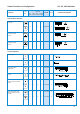
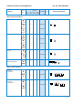
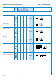
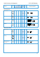
Switch Function and Configuration CG, CH, CHR Switches
1
Connection diagrams for CHR switches on request.
2
incl. slip clutch
Function
Escutch.
Plate
Code
Stages
Connection Diagram
1
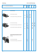
Motor Control Switches
A440-600
A440-620
A466-600
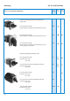
A441-600
A441-620
A442-600
A442-620
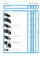
A444-600
A444-620
A468-600
A468-620
2 speed single winding
2 speed single winding
without „OFF“
2 speed single winding
with center „OFF“
2 speed single winding
reversing
2 speed single winding
for use with contactors
2 speed reversing for
2 way operation with slip
clutch for „OFF“ load use
4
4
4
4
4
6
6
5
5
10
2
10
2
I
I
I
I
I
I
I
I
I
I
I
I
I
I
I
I
I
I
I
I
I
I
I
I
I
I
I
I
I
I
I
I
I
I
I
I
f
1
02
f
OFF 2
1
f
12
f
0
12
f
OFF
12
f
0
1
22
1
f
OFF
1
22
1
f
1
02
f
OFF 2
1
f
0
1
2
1
2
f
OFF
1
2
1
2
L1
L2
2
5
R
S
14
L3
T
11
U
V
T2
W
T3
T1
631 813
L1
L2
2
5
R
S
14
L3
T
11
U
V
T2
W
T3
T1
631 813
L1
L2
2
5
R
S
14
L3
T
11
U
V
T2
W
T3
T1
631 813
L1
L2
1
5
R
S
21
L3
T
22
U
V
T2
W
T3
T1
11 13 9 15 24
L1
L2
2
5
R
S
14
L3
T
11
U
V
T2
W
T3
T1
631 813
17 18 19
N
O
95 96
L1
L2
2
26
R
S
28
L3
T
1
U
T1
9
X
T4
7
14
V
T2
11
Y
T5
29
16
W
T3
6
Z
T6
25