K R A ME R E LE CT R O N IC S L T D .
Contents 1 Introduction 1 2 2.1 2.2 2.3 3 3.1 3.2 Getting Started Achieving the Best Performance Safety Instructions Recycling Kramer Products Overview Defining the VS-88DVI 8x8 DVI Matrix Switcher Using the IR Transmitter 2 2 3 3 4 4 7 4 Installing in a Rack 8 5 Connecting the VS-88DVI 6 6.1 6.2 6.3 6.4 6.5 6.
1 Introduction Welcome to Kramer Electronics! Since 1981, Kramer Electronics has been providing a world of unique, creative, and affordable solutions to the vast range of problems that confront video, audio, presentation, and broadcasting professionals on a daily basis.
2 Getting Started We recommend that you: • Unpack the equipment carefully and save the original box and packaging materials for possible future shipment • Review the contents of this user manual i 2.1 Go to http://www.kramerelectronics.com to check for up-to-date user manuals, application programs, and to check if firmware upgrades are available (where appropriate).
2.2 Safety Instructions ! 2.3 Caution: There are no operator serviceable parts inside the unit Warning: Use only the power cord that is supplied with the unit Warning: Do not open the unit.
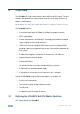
3 Overview The VS−88DVI is a high−performance matrix switcher for DVI signals. The unit reclocks and equalizes the signal and can route any or all inputs to any or all outputs simultaneously. DVI-D (Digital). Note that only the digital signal (DVI-D) is available on the DVI connector. The VS-88DVI features: • A maximum data rate of 6.75Gbps (2.
VS-88DVI – Overview Figure 1: VS-88DVI 8x8 DVI Matrix Switcher Front Panel # Feature Function 1 IR Receiver LED The yellow LED is illuminated when receiving signals from the infrared remote control transmitter 2 POWER LED Illuminates green when receiving power 3 ALL Button Use ALL to select all outputs (see Section 6.1) 4 OFF Button Use OFF to disconnect one or all outputs (see Section 6.
6 Figure 2: VS-88DVI 8x8 DVI Matrix Switcher Rear Panel # Feature Function 12 OUT DVI Connectors Connect to the DVI acceptors (from 1 to 8) 13 IN DVI Connectors Connect to the DVI sources (from 1 to 8) 14 RS-232 9-pin D-sub Port Connects to the PC or the RS-232 Remote Controller 15 Ethernet Connector Connects to the PC or other Ethernet Controller 16 RESET Button Press the reset button to reset to the Ethernet factory default definitions: IP number − 192.168.1.39 Mask – 255.255.255.
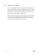
3.2 Using the IR Transmitter You can use the RC-IR3 IR transmitter to control the machine via the built-in IR receiver on the front panel or, instead, via an optional external IR receiver (Model: C-A35M/IRR-50). The external IR receiver can be located up to 15 meters away from the machine. This distance can be extended to up to 60 meters when used with three extension cables (Model: C-A35M/A35F-50).
4 Installing in a Rack This section provides instructions for rack mounting the unit.
5 Connecting the VS-88DVI i Always switch off the power to each device before connecting it to your VS-88DVI. After connecting your VS-88DVI, connect its power and then switch on the power to each device. To connect the VS-88DVI, as the example in Figure 3 illustrates, do the following: 1. Connect up to eight DVI sources (for example, computer graphics sources) to the IN DVI connectors. You do not have to connect all the inputs and the outputs. 2.
Figure 3: Connecting the VS-88DVI 8x8 DVI Matrix Switcher 10 VS-88DVI - Connecting the VS-88DVI
6 Operating the VS-88DVI This section describes how to: 6.1 • Route inputs to outputs (see Section 6.1) • Disconnect outputs (see Section 6.2) • Store and recall a setup (see Section 6.3) • Acquire the EDID (see Section 6.4) • Control the machine via RS-232 (see Section 6.5) • Control the machine via the Ethernet port (see Section 6.
Figure 4: SELECTOR Buttons The gray numbers (1 to 16) in Figure 4 that illustrate the corresponding store/recall configuration numbers, are for the purpose of illustration only and do not actually appear on the buttons To store a setup: 1. Set the machine to the desired input/output connection setup. 2. Press the STO button. The STO button flashes. 3. Select an OUT or IN SELECT button to store the machine setup (for example, OUT 5). 4. Press the LOCK button to store the current setup.
6.4 Acquiring the EDID You can acquire the EDID from: 6.4.1 • A single connected output (see Section 6.4.1) • Several sets of inputs and outputs (see Section 6.4.2) • The default EDID (see Section 6.4.3) Acquiring an EDID from a Single Connected Output To acquire or change the EDID of a new output display: 1. Turn ON the VS-88DVI. 2. Connect the required acceptor to the output from which you want to acquire the EDID. 3. Press the EDID and STO buttons simultaneously and hold them for 3 seconds.
6.4.2 Acquiring an EDID from Several Sets of Inputs and Outputs To acquire the EDID from several sets of inputs and outputs (for example, OUT 1 to IN 1 and OUT 6 to IN 3), do the following: 1. Enter the EDID mode: Turn ON the VS-88DVI Connect the required acceptors to the outputs from which you want to acquire the EDID Press the EDID and STO buttons simultaneously and hold them for 3 seconds. Both buttons flash. 2.
6.4.3 Acquiring the Default EDID To reset to the default EDID, do the following: 1. Turn ON the VS-88DVI. 2. Press the EDID and STO buttons simultaneously and hold them for 3 seconds. Both buttons flash. 3. Press the SELECT IN button to which the EDID is copied. The selected input number flashes on the display. 4. Press the OFF button until a "0" (zero) appears on the display. 5. Press the EDID button. The process is complete when the display returns to normal. 6.
Method B—Connect the RS-232 9-pin D-sub port on the unit via a straight (flat) cable to the null-modem adapter, and connect the null-modem adapter to the RS-232 9-pin D-sub port on the PC. The straight cable usually contains all nine wires for a full connection of the D-sub connector.
Figure 6: Local Area Connection Properties Window 6. Select Use the following IP Address, and fill in the details as shown in Figure 7. 7. Click OK.
6.6.2 Connecting the Ethernet Port via a Network Hub (StraightThrough Cable) You can connect the Ethernet port of the VS-88DVI to the Ethernet port on a network hub or network router, via a straight through cable with RJ-45 connectors. 6.6.3 Control Configuration via the Ethernet Port To control several units via the Ethernet, connect the Master unit (Machine # 1) via the Ethernet port to the LAN port of your PC. Use your PC initially to configure the settings (see Section 6.6).
7 Technical Specifications INPUTS: 8 DVI, 1.2Vpp on DVI Molex 24-pin female connectors; DDC signal 5Vpp (TTL) OUTPUTS: 8 DVI, 1.2Vpp on DVI Molex 24-pin female connectors; DDC signal 5Vpp (TTL) MAX. DATA RATE: Supports up to 6.75Gbps (2.25Gbps per graphic channel) COMPLIANCE WITH STANDARDS: Supports DVI 1.
8 Hex Table The following table lists the Hex values for a single machine (MACHINE # 1): Switching Video Channels OUT 1 OUT 2 OUT 3 OUT 4 OUT 5 OUT 6 OUT 7 OUT 8 IN 1 01 81 81 81 01 81 82 81 01 81 83 81 01 81 84 81 01 81 85 81 01 81 86 81 01 81 87 81 01 81 88 81 IN 2 01 82 81 81 01 82 82 81 01 82 83 81 01 82 84 81 01 82 85 81 01 82 86 81 01 82 87 81 01 82 88 81 IN 3 01 83 81 81 01 83 82 81 01 83 83 81 01 83 84 81 01 83 85 81 01 83 86 81 01 83 87 81 01 83 88 81 IN 4 01 84 81 81 01 84 82 81 01
9 Protocol 2000 This RS-232/RS-485 communication protocol uses four bytes of information as defined below. For RS-232, a null-modem connection between the machine and controller is used. The default data rate is 9600 baud, with no parity, 8 data bits and 1 stop bit. Note: Compatibility with Kramer’s Protocol 2000 does not mean that a machine uses all of the commands below. Each machine uses a sub-set of Protocol 2000, according to its needs. 9.
9.
NOTE 8 – The reply is as in NOTE 4 above, except that the OUTPUT is assigned with the value 0 if the setup is not defined / no valid input is detected; or 1 if it is defined / valid input is detected. NOTE 13 – This is a request to identify the switcher/s in the system. If the OUTPUT is set as 0, and the INPUT is set as 1, 2, 5 or 7, the machine sends its name. The reply is the decimal value of the INPUT and OUTPUT.
For the latest information on our products and a list of Kramer distributors, visit our Web site where updates to this user manual may be found. We welcome your questions, comments, and feedback. Web site: www.kramerelectronics.com E-mail: info@kramerel.