K R A ME R E LE CT R O N IC S L T D .
Contents 1 Introduction 1 2 2.1 2.2 Getting Started Achieving the Best Performance Recycling Kramer Products 2 2 3 3 Overview 4 4 Defining the VS-401USB 4x1 USB Switcher 5 5 5.1 Connecting the VS-401USB Connecting a PC 6 7 6 6.1 7 Operating the VS-401USB The Application Software Firmware Upgrade 8 8 9 8 Technical Specifications 10 9 Default Communication Parameters 11 10 Kramer Protocol 2000 12 11 11.1 11.
1 Introduction Welcome to Kramer Electronics! Since 1981, Kramer Electronics has been providing a world of unique, creative, and affordable solutions to the vast range of problems that confront the video, audio, presentation, and broadcasting professional on a daily basis.
2 Getting Started We recommend that you: • Unpack the equipment carefully and save the original box and packaging materials for possible future shipment • Review the contents of this user manual • Use only the power cord that is supplied with this machine i 2.1 Go to http://www.kramerelectronics.com to check for up-to-date user manuals, application programs, and to check if firmware upgrades are available (where appropriate).
2.2 Recycling Kramer Products The Waste Electrical and Electronic Equipment (WEEE) Directive 2002/96/EC aims to reduce the amount of WEEE sent for disposal to landfill or incineration by requiring it to be collected and recycled. To comply with the WEEE Directive, Kramer Electronics has made arrangements with the European Advanced Recycling Network (EARN) and will cover any costs of treatment, recycling and recovery of waste Kramer Electronics branded equipment on arrival at the EARN facility.
3 Overview The Kramer VS-401USB is a high quality 4x1 USB switcher. It accepts up to four USB devices and switches the selected device to the host. The VS-401USB always powers the selected port as well as the three that were not selected, (allowing attached USB units to be charged, for example). In particular, the VS-401USB features: 4 • Four DEVICE SELECT buttons • Hi speed USB revision 2.
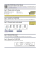
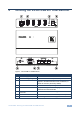
4 Defining the VS-401USB 4x1 USB Switcher Figure 1: VS-401USB 4x1 USB Switcher # 1 Feature HOST USB (type B) Port Connects to the host Function 2 DEVICE USB (type A) port Connects to a USB device (from 1 to 4) 3 PROG Button Push in for “Program” using a small screwdriver to upgrade to the latest Kramer firmware via RS-232, or release for “Normal” (the factory default) 4 5V DC +5V DC connector for powering the unit 5 IR Receiver The yellow LED lights when receiving signals from the infrared
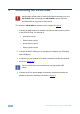
5 Connecting the VS-401USB ! Always switch off the power to each device before connecting it to your VS-401USB. After connecting your VS-401USB, connect its power and then switch on the power to each device. To connect the VS-401USB as illustrated in the example in Figure 2: 1. Connect the USB devices (for example, hard drives and/or memory sticks) to the DEVICE ports. For example, a: Hard drive to port 1 Memory stick to port 2 Smart phone to port 3 Memory stick to port 4 2.
Figure 2: Connecting to the VS-401USB 5.1 Connecting a PC You can connect to the VS-401USB via an RS-232 connection using, for example, a PC. Note that a null-modem adapter/connection is not required. To connect to the VS-401USB via RS-232, connect the RS-232 9-pin D-sub rear panel port on the VS-401USB unit via a 9-wire straight cable (only pin 2 to pin 2, pin 3 to pin 3, and pin 5 to pin 5 need to be connected) to the RS-232 9-pin D-sub port on your PC.
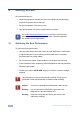
6 Operating the VS-401USB You can operate the VS-401USB via the front panel buttons by pressing one of the four DEVICE SELECT buttons to select a device to switch to the HOST. You can also use the application software (see Section 6.1) or the RC-IR3 IR remote control transmitter to operate the VS-401USB. 6.1 The Application Software Use the K-SINGLE control application software to control the VS-401USB via the Ethernet or RS-232 9-pin D-sub.
7 Firmware Upgrade You can upgrade the VS-401USB via the Kramer K-UPLOAD software. i The latest version of K-UPLOAD and installation instructions, as well as the application software and its user guide, can be downloaded from the Kramer Web site at www.kramerelectronics.
8 Technical Specifications DEVICE PORTS: 4 x USB (type A) ports HOST PORT: 1 USB (type B) port CONTROL: Front panel buttons, IR remote control, RS-232 on a 9-pin D-sub connector POWER SOURCE: 5V DC, 3.2A OPERATING TEMPERATURE: 0° to +40°C (32° to 104°F) STORAGE TEMPERATURE: -40° to +70°C (-49° to 158°F) HUMIDITY: 10% to 90%, RHL non-condensing DIMENSIONS: 12cm x 7.15cm x 2.44cm (4.7" x 2.81" 0.96") W, D, H WEIGHT: 0.3kg (0.67lbs) approx.
9 Default Communication Parameters RS-232 Protocol 2000 Protocol 3000 (Default) Baud Rate: 9600 Baud Rate: Data Bits: 8 Data Bits: 115200 8 Stop Bits: 1 Stop Bits: 1 Parity: None Parity: None Command Format: HEX Command Format: ASCII Example (Output 1 to Input 1): 0x01, 0x81, 0x81, 0x81 Example (Output 1 to Input 1): #AV 1>1 Switching Protocol P2000 -> P3000 P3000 -> P2000 Command: 0x38, 0x80, 0x83, 0x81 Command: Front Panel: Press and hold Output 1 and Output 3 simultaneou
10 Kramer Protocol 2000 The Kramer Protocol 2000 for RS-232/RS-485 communication uses four bytes of information as defined below. All the values in the table are decimal, unless otherwise stated.
Instruction Codes for Protocol 2000 Instruction Definition for Specific Instruction # Description Input Output 1 SWITCH VIDEO 5 56 REQUEST STATUS OF A VIDEO OUTPUT CHANGE TO ASCII 61 IDENTIFY MACHINE 62 DEFINE MACHINE Set equal to video input which is to be switched (0 = disconnect) Set as SETUP # 0 1 - video machine name 2 - audio machine name 3 - video software version 4 - audio software version 5 - RS422 controller name 6 - RS422 controller version 7 - remote control name 8 - remote software ver
11 Protocol 3000 The VS-401USB can be operated using serial commands from a PC, remote controller or touch screen using the Kramer Protocol 3000. This section describes: 11.1 • Kramer Protocol 3000 syntax (see Section 11.1) • Kramer Protocol 3000 commands (see Section 11.2) Kramer Protocol 3000 Syntax 11.1.1 Host Message Format Start Address (optional) Body Delimiter # Destination_id@ Message CR 11.1.1.
11.1.3 Command Terms Command A sequence of ASCII letters ('A'-'Z', 'a'-'z' and '-'). Command and parameters must be separated by at least one space. Parameters A sequence of alphanumeric ASCII characters ('0'-'9','A'-'Z','a'-'z' and some special characters for specific commands). Parameters are separated by commas. Message string Every command entered as part of a message string begins with a message starting character and ends with a message closing character.
11.1.4 Entering Commands You can directly enter all commands using a terminal with ASCII communications software, such as HyperTerminal, Hercules, etc. Connect the terminal to the serial or Ethernet port on the Kramer device. To enter CR press the Enter key. ( LF is also sent but is ignored by command parser). For commands sent from some non-Kramer controllers like Crestron, some characters require special coding (such as, /X##). Refer to the controller manual. 11.1.
11.
For the latest information on our products and a list of Kramer distributors, visit our Web site where updates to this user manual may be found. We welcome your questions, comments, and feedback. Web site: www.kramerelectronics.com E-mail: info@kramerel.