
User Manual


KRAMER: SIMPLE CREATIVE TECHNOLOGY
Contents
ii
7.5.1
Storing Setups 33
7.5.2
Recalling Setups 33
7.6
Using the DEFAULT SETUP Button (Unity Setting) 34
7.7
Choosing the FOLLOW or the BREAKAWAY Modes 35
7.8
Using the LOCK Button 36
8
The MENU Commands 37
8.1
Selecting the SYNC Configuration 39
8.2
Selecting the INTERFACE Configuration 39
8.3
Selecting the Interface REPLY Configuration 40
8.4
Selecting the PROTOCOL Configuration 40
8.5
Selecting the DEFAULT Setup Configuration 40
8.6
Selecting the store DEFAULT Setup Configuration 40
8.7
The Main Firmware Version 41
8.8
Selecting the TOTAL RESET Option 41
9
Flash Memory Upgrade 42
9.1
Switcher Flash Memory Upgrade 42
9.1.1
Downloading from the Internet 42
9.1.2
Connecting the PC to the RS-232 Port 42
9.1.3
Upgrading Firmware 43
9.2
Ethernet Flash Memory Upgrade 47
9.2.1
Downloading from the Internet 47
9.2.2
Connecting the PC to the RS-232 Port 47
9.2.3
Upgrading Firmware 48
10
Technical Specifications 49
11
Communication Protocols 49
11.1
The Kramer 2000 Communication Protocol 49
11.2
ASCII Protocol: General 54
11.2.1
ASCII Protocol: Description 54
Figures
Figure 1: VS-3232V 32x32 Video Matrix Switcher Front Panel 5
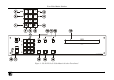
Figure 2: VS-3232V 32x32 Video Matrix Switcher Rear Panel 7
Figure 3: Configuring the VS-3232V for Composite Video 12
Figure 4: Configuring a 32x32 s-Video (YC) Switcher with two VS-3232V Switchers 14
Figure 5: Configuring a 32x32 YUV (RGB) Switcher with three VS-3232V Switchers 15
Figure 6: Dipswitches 16
Figure 7: Connecting a PC to Three VS-3232V Units 20
Figure 8: RS-485 Connector PINOUT 22
Figure 9: Connecting the RS-485 Connectors between two VS-3232V Units 23
Figure 10: RS-485 Control Interface and SYNC Connections for Component Switcher 24
Figure 11: Local Area Connection Properties Window 26
Figure 12: Internet Protocol (TCP/IP) Properties Window 27
Figure 13: Default Startup Status Display Sequence 28
Figure 14: Setting the SYNC Configuration (an example) 38