
User Manual


Connecting the Video Matrix Switcher
17
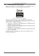
6.3.1 Setting the MACHINE #
To control a unit remotely via RS-232, RS-485, IR or the Ethernet, each unit
has to be identified via its unique Machine #. Set the Machine #
1
on a
VS-3232V unit according to Table 4.
Table 4: Machine # Dipswitch Settings
Mach. # DIP 1 DIP 2 DIP 3 DIP 4 Mach. # DIP 1 DIP 2 DIP 3 DIP 4
1 ON OFF OFF OFF 9 ON OFF OFF ON
2 OFF ON OFF OFF 10 OFF ON OFF ON
3 ON ON OFF OFF 11 ON ON OFF ON
4 OFF OFF ON OFF 12 OFF OFF ON ON
5 ON OFF ON OFF 13 ON OFF ON ON
6 OFF ON ON OFF 14 OFF ON ON ON
7 ON ON ON OFF 15 ON ON ON ON
8 OFF OFF OFF ON
6.3.2 Understanding the System Mode
Though the terms audio-follow-video
2
and audio breakaway
3
are well known,
there may be signals other than audio signals that need to be switched
simultaneously and at other times, need to be switched independently.
For example:
Non-linear editing systems that combine video with analog audio or with
digital audio
Duplication systems, that produce Master tapes from programs with
different formats such as composite analog, component analog and
component digital
The term FOLLOW-SYSTEM
4
indicates the most common case where
any type of signal can follow one or more other signals.
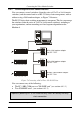
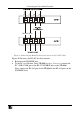
DIP 5 defines whether the VS-3232V unit can communicate with other
switchers via a common control line.
You can set DIP 5 OFF to disable the FOLLOW-SYSTEM mode when
setting a standalone switcher
5
application, including standalone multi-
channel video switcher applications
6
.
1 When using a single unit, set the unit to MACHINE # 1
2 Video and the audio channels switch simultaneously in the same way
3 Audio channels switch independently from the video channels
4 Instead of Audio-Follow-Video
5 See section 6.1
6 See section 6.2