
User Manual


KRAMER: SIMPLE CREATIVE TECHNOLOGY
Connecting the Video Matrix Switcher
16
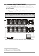
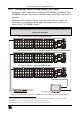
6.2.3 Configuring a 32x32 RGBS Switcher (Four Units)
Configure four VS-3232V switchers as a 32x32 video matrix switcher for
RGBS
1
, in a similar way to how Figure 5 in section 6.2.2 illustrates combining
three VS-3232V switchers for YUV (RGB).
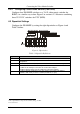
6.3 Dipswitch Settings
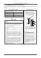
Configure the VS-3232V by setting the eight dipswitches as Figure 6 and
Table 3 define:
RS-232 NULL-MODEM
MACHINE #
SYSTEM MODE SLAVE MODE
RS-485
TERMINATION
Figure 6: Dipswitches
Table 3: Dipswitch Definitions
Dipswitch # Function:
1-4 Set the MACHINE # (see Table 4 in section 6.3.1)
5 Enables (ON) or disables (OFF) the FOLLOW SYSTEM MODE in a multi-switcher
configuration
6 Enables (ON) or disables (OFF) the SLAVE mode in a multi-channel configuration
7 Disables the use of a null modem adapter
2
with RS-232 as follows:
Set OFF for RS-232 input connection via a null modem adapter
Set ON for RS-232 input connection without a null modem adapter
8 Set ON for RS-485 termination for the first and the last machine (RS-485 line
terminates with 110); for others set OFF (RS-485 line is open)
1 The S signal must be composite video SYNC (analog), not TTL
2 See section 6.4.1