
User Manual


Connecting the Video Matrix Switcher
15
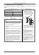
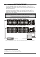
6.2.2 Configuring a 32x32 YUV/RGB Switcher (Three Units)
Configure a 32x32 video matrix switcher for YUV/RGB by combining
1
three
VS-3232V switchers. Note that the machine number on all three units must be
identical.
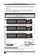
Although in the example in Figure 5 only one input
2
and one output
3
are
connected, you can connect all the inputs and outputs in the same way to
create a 32x32 YUV/RGB switcher.
Connect the communication line via the RS-232 or RS-485 control interface as
section 6.4 describes.
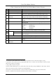
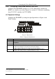
Component
Video Player
YUV/RGB Display
Y/G Channel Switcher - Master
( )
Set DIP 6 to OFF
V/R Channel Switcher - Slave ( )
Set DIP 6 to ON
U/B Channel Switcher - Slave
( )
Set DIP 6 to ON
V/R
V/R
U/B
U/B
Y/G
Y/G
Figure 5: Configuring a 32x32 YUV (RGB) Switcher with three VS-3232V Switchers
1 For a description of how to connect the RS-485 connectors between the VS-3232V switchers, refer to section 6.4.2
2 The INPUT 1 connectors on the Y switcher, the U switcher and the V switcher
3 The OUTPUT 32 connectors on the Y switcher, the U switcher and the V switcher