
User Manual


KRAMER: SIMPLE CREATIVE TECHNOLOGY
Your Video Matrix Switcher
8
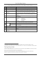
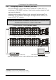
Table 2: Rear Panel VS-3232V 32x32 Video Matrix Switcher Features
# Feature Function
1 INPUT BNC Connectors Connect to the video sources (from 1 to 32)
2 OUTPUT BNC Connectors Connect to the video acceptors (from 1 to 32)
3 REMOTE IR Opening
1
Connects to an external IR receiver unit
2
for controlling the machine via
an IR remote controller (instead of using the front panel IR receiver)
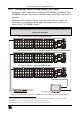
4 RS-485 Detachable Terminal
Block Port
The SYNC and the G PINs are for vertical sync and ground
connection respectively, and the B and A PINs are for RS-485
5 FLASH MAIN Button Push in
3
to upgrade the switcher microcontroller to the latest Kramer
firmware (see
section 9.1), or release (the factory default) for normal
operation
6 ETHERNET Connector Connects to the PC or other Serial Controller through computer
networking LAN
7 FACTORY RESET Button Press to reset to factory default definitions
4
:
IP Address: 192.168.1.39
Mask: 255.255.255.0
Gateway: 192.168.1.1
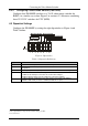
8 FLASH – Normal Switch Push in
3
to upgrade the ETH FLASH firmware version (see section
9.2), or release (the factory default) for normal operation
9 IN DB 9F Port Connects to the PC or the Remote Controller
5
10
RS-232
OUT DB 9M Port Connects to the RS-232 IN DB 9F port of the next unit in the daisy-
chain connection
11 Power Connector with Fuse AC connector enabling power supply to the unit
12 SETUP Dipswitches Dipswitches for setup of the unit (see section 6.2.3)
13
TERM 75
Button
Press to terminate the GENLOCK SYNC with 75 or release for
looping
6
14 GENLOCK Double BNC
Connectors
For GENLOCK SYNC input/loop
1 Covered by a cap. The 3.5mm connector at the end of the internal IR connection cable fits through this opening
2 Optional. Can be used instead of the front panel (built-in) IR receiver to remotely control the machine (only if the internal
IR connection cable has been installed)
3 Using a small screwdriver if required
4 Turn the machine OFF using the power switch and then turn it ON while pressing the ETH Factory Reset button. The unit
will power up and load its memory with the factory default definitions
5 If the unit is not the first unit in the line, connects to the RS-232 OUT DB 9F port of the previous unit in the line
6 Push in to terminate the sync line. Push out when the sync line extends to another unit