K R A ME R E LE CT R O N IC S L TD .
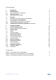
Contents 1 Introduction 1 2 2.1 2.2 2.3 3 3.1 Getting Started Achieving the Best Performance Safety Instructions Recycling Kramer Products Overview Defining the VS-21HDCP-IR 2x1 DVI Switcher 2 2 3 3 4 4 4 4.1 4.2 4.3 Connecting the VS-21HDCP-IR Controlling the VS-21HDCP-IR via RS-232 Using the Remote Control Transmitter Controlling via the Remote Terminal Block Connector 6 7 8 8 5 Acquiring an EDID 6 6.1 7 7.1 7.
1 Introduction Welcome to Kramer Electronics! Since 1981, Kramer Electronics has been providing a world of unique, creative, and affordable solutions to the vast range of problems that confront video, audio, presentation, and broadcasting professionals on a daily basis.
2 Getting Started We recommend that you: Unpack the equipment carefully and save the original box and packaging materials for possible future shipment Review the contents of this user manual i 2.1 Go to http://www.kramerelectronics.com to check for up-to-date user manuals, application programs, and to check if firmware upgrades are available (where appropriate).
2.2 Safety Instructions ! 2.3 Caution: There are no operator serviceable parts inside the unit Warning: Use only the Kramer Electronics input power wall adapter that is provided with the unit Warning: Disconnect the power and unplug the unit from the wall before installing Recycling Kramer Products The Waste Electrical and Electronic Equipment (WEEE) Directive 2002/96/EC aims to reduce the amount of WEEE sent for disposal to landfill or incineration by requiring it to be collected and recycled.
3 Overview The high quality Kramer VS-21HDCP-IR is an HDCP (High-Bandwidth Digital Content Protection) compatible 2x1 DVI Switcher that accepts two DVI inputs— letting you select either DVI input using a pushbutton located on the front panel— and routes the selected DVI input signal to the DVI output. DVI-D (Digital). Note that only the digital signal (DVI-D) is available on the DVI connector. The VS-21HDCP-IR features: A maximum data rate of 6.75Gbps (2.
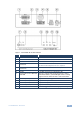
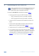
Figure 1: VS-21HDCP-IR 2x1 DVI Switcher # Feature 1 INPUT 1 DVI Connector Connect to the DVI source 1 2 INPUT 2 DVI Connector Connect to the DVI source 2 3 OUTPUT DVI Connector Connect to the DVI acceptor 4 RS-232 9-pin D-sub Connector Connects to the PC or Serial Controller 5 REMOTE Terminal Block Connectors Connect to a contact closure switch (see Section 4.
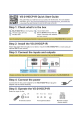
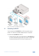
4 Connecting the VS-21HDCP-IR i Always switch off the power to each device before connecting it to your VS-21HDCP-IR. After connecting your VS-21HDCP-IR, connect its power and then switch on the power to each device. To connect the VS-21HDCP-IR as illustrated in the example in Figure 2: 1. Connect up to two DVI sources to the INPUT connectors, as follows: INPUT 1 connector to DVI source 1 (for example, a computer) INPUT 2 connector to DVI source 2 (for example, a set top box) 2.
Figure 2: Connecting the VS-21HDCP-IR 2x1 DVI Switcher 4.1 Controlling via RS-232 You can connect to the VS-21HDCP-IR via an RS-232 connection using, for example, a PC. Note that a null-modem adapter/connection is not required.
4.2 Controlling via the Remote Control Transmitter You can use the remote control transmitter to switch INPUT 1 or 2 to the output. Before doing so, set it to work with the VS-21HDCP-IR by assigning a GROUP number. The setup parameters for the remote control transmitter are as follows: router number = 1 (default); group number = 11, single digit mode (default), video (default). For further details, see the RC-IR3 user manual.
5 Acquiring an EDID Initially, the VS-21HDCP-IR operates with the factory default EDID. This lets you connect the power before connecting one of the acceptors or the source. You can acquire the EDID from the output to one of the two inputs, or set the acquired EDID and the default EDID to both inputs. To acquire the EDID, do the following: 1. Connect the power. 2. Connect the output. 3. Press and hold the SELECT button.
6 Technical Specifications INPUTS: 2 DVI-D on DVI-I connectors, 1.2Vpp; DDC signal 5Vpp (TTL) OUTPUT: 1 DVI-D on a DVI-I connector; DDC signal 5Vpp (TTL) BANDWIDTH: 6.75Gbps (2.25Gbps per graphic channel) POWER CONSUMPTION: 5V DC, 250mA OPERATING TEMPERATURE: 0° to +40°C (32° to 104°F) STORAGE TEMPERATURE: -40° to +70°C (-40° to 158°F) HUMIDITY: 10% to 90%, RHL non-condensing DIMENSIONS: 14.3cm x 12.2cm x 4.36cm (5.63" x 4.8" x 1.72", W, D, H) WEIGHT: 0.3kg (0.67lbs) approx.
7 Protocol 2000 This RS-232/RS-485 communication protocol uses four bytes of information as defined below. For RS-232, a null-modem connection between the machine and controller is used. The default data rate is 9600 baud, with no parity, 8 data bits and 1 stop bit. Note: Compatibility with Kramer’s Protocol 2000 does not mean that a machine uses all of the commands below. Each machine uses a sub-set of Protocol 2000, according to its needs. 7.
7.2 Instruction Codes All the values in the table are decimal, unless otherwise stated Instruction Codes for Protocol 2000 # 1 Instruction Description SWITCH VIDEO Definition for Specific Instruction Input Output Set equal to video input that is Set equal to video output that is switched switched (0 = disconnect) (0 = to all the outputs) Notes 2, 15 NOTES on the above table: NOTE 2 – These are bi-directional definitions. If the switcher receives the code, it performs the instruction.
8 Protocol 3000 Syntax With Kramer Protocol 3000 you can control the VS-21HDCP-IR from any standard terminal software (for example, the Windows® HyperTerminal Application). This RS-232/RS-485 communications protocol uses a data rate of 115,200 baud, no parity, 8 data bits, and 1 stop bit. 8.1 Host Message Format Start Address (optional) Body Delimiter # Destination_id@ Message CR 8.1.
8.3 Command Terms Command A sequence of ASCII letters ('A'-'Z', 'a'-'z' and '-'). Command and parameters must be separated by at least one space. Parameters A sequence of alphameric ASCII characters ('0'-'9','A'-'Z','a'-'z' and some special characters for specific commands). Parameters are separated by commas. Message string Every command entered as part of a message string begins with a message starting character and ends with a message closing character. Note: A string can contain more than one command.
Command chain separator character When a message string contains more than one command, a pipe ( '|' ) character separates each command. Spaces between parameters or command terms are ignored. 8.4 Entering Commands You can directly enter all commands using a terminal with ASCII communication software, such as HyperTerminal, Hercules, etc. Connect the terminal to the serial, Ethernet, or USB port on the Kramer device. To enter CR , press the Enter key.
8.8 Maximum String Length 64 characters 8.9 Backward Support Protocol 2000 is transparently supported by Protocol 3000. You can switch between protocols using a switch protocol command from either platform. 8.10 Commands 8.10.1 Help Commands Command Syntax Response Protocol handshaking #CR ~OKCRLF 8.10.2 Common Commands Command Description Syntax Response MODEL? VERSION? Read device model MODEL? MODEL MACHINE_MODEL Read device firmware version VERSION? VERSION MAJOR .MINOR .BUILD .
For the latest information on our products and a list of Kramer distributors, visit our Web site where updates to this user manual may be found. We welcome your questions, comments, and feedback. Web site: www.kramerelectronics.com E-mail: info@kramerel.