
Owner's manual


KRAMER: SIMPLE CREATIVE TECHNOLOGY
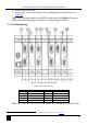
Defining the VS-1616D 16x16 Digital Matrix Switcher
10
Table 3: VS-1616D 16x16 Digital Matrix Switcher Rear Panel Features
#
Feature
Function
21 AC Mains Power Module Fuse holder and power cord socket. Connect to the AC
mains supply
22 RS-232 9-pin D-sub Port Connects to the remote operation PC or remote controller
1
(see
Section 6.4
23
)
IN 1~4, 5~8 Connectors
INPUTS
Connect to the relevant video sources, depending on the
cards installed (1 to 8, see
Section 6
24
)
IN 9~12, 13~16
Connectors
Connect to the relevant video sources, depending on the
cards installed (9 to 16, see
Section 6
25
)
TEST Module Signal generator module for testing video outputs (see
Section 10
26
)
RESOLUTION DIP-switches Set the resolution for video generated by the Test module
(see
Section 10.2
27
)
NET Ethernet RJ-45 Connector Connect to a PC or controller via the Ethernet LAN (see
Section 6.5
LINK LED flashes when communication is active. POWER
LED lights when the interface receives power
).
28 OUT 1~4, 5~8
Connectors
OUTPUTS
Connect to the relevant video acceptors, depending on the
cards installed (1 to 8, see
Section 6
29
)
OUT 9~12, 13~16
Connectors
Connect to the relevant video acceptors, depending on the
cards installed (9 to 16, see
Section 6
30
)
Test Module Output Connector Connect to one of the relevant video inputs to aid in
troubleshooting (see
Section 10.4
31
)
PATTERN Button Press the button repeatedly to change the video pattern
generated by the Test module (see
Section 10.3
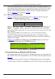
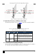
4.1 Using the IR Transmitter
)
You can use the RC-IR3 IR transmitter to control the machine via the built-in IR
receiver on the front panel.
1 If the unit is not the first unit in the line, connects to the RS-232 OUT 9-pin DB port of the previous unit in the line