
User Manual


VP-8x8 - Connecting the VP-8x8 8x8 VGA/UXGA Matrix Switcher
9
9
5 Connecting the VP-8x8 8x8 VGA/UXGA
Matrix Switcher
Always switch off the power to each device before connecting it to your
VP-8x8. After connecting your VP-8x8, connect its power and then
switch on the power to each device.
This section describes how to:
Connect the VP-8x8 rear panel (see Section 5.1)
Connect the VP-8x8 to a controlling device via RS-232 (see Section 5.2),
RS-485 (see Section 5.3) and/or the Ethernet (see Section 5.4)
Set the DIP-switches (see Section 5.5)
Connect several VP-8x8 machines (see Section 5.6)
5.1 Connecting the VP-8x8 Rear Panel
To connect the VP-8x8, do the following:
Switch OFF the power on each device before connecting it to your VP-8x8. After connecting your VP-8x8,
switch on its power and then switch on the power on each device. DO NOT push in the rear panel Flash
Program “Program” button (item 14 in Figure 2) and DO NOT push in the underside Flash Program “Reset”
button. These are only used for upgrading to the latest Kramer firmware.
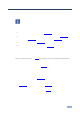
1. Connect up to 8 VGA/UXGA computer graphics sources to the input
connectors (see the example in Figure 4).
2. Connect the 8 output connectors to up to 8 VGA/UXGA video acceptors.
When less than eight outputs are required, connect only those outputs of the VP-8x8 that are
required, and leave the other outputs unconnected
3. Set the DIP-switches (see Section 5.4).
4. Connect a PC and/or controller (if required) to the RS-232 port (see
Section 5.2) and/or RS-485 port (see Section 5.2).
5. Connect the power cord (not shown in Figure 4).
i