
User Manual


KRAMER ELECTRONICS LTD.
9
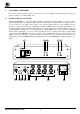
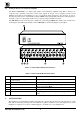
7. CONNECTING TO VIDEO DEVICES
Video sources and output devices (such as amplifiers or recorders) may be connected to the amplifier through
the BNC connectors located at the back of the machine. Please keep in mind that the output signal format must
match that of the input signal format.
8. CONNECTING TO AUDIO DEVICES
Audio sources and output devices (such as amplifiers or recorders) may be connected to the amplifier through
the RCA type connectors (VM-10AN) located at the back of the machines.
9. USING THE VM VIDEO/AUDIO AMPLIFIERS
9.1
Turning On The Amplifier
NOTES
1. Amplifier should only be t
urn
ed on after all connections are completed and all
source devices have been t
urn
ed on. Do not attempt to connect or disconnect
any video, audio or control signals to the amplifier while it is t
urn
ed on!
2. The socket-outlet should be near the equipment and should be easily
accessible. To fully disconnect equipment, remove power cord from its socket.
1) Press the toggle switch on the far-left front panel to the up position. In the up position, the toggle switch
glows, and the active input button illuminates as well.
2) Operate the sources and acceptors.
9.2
Looping
The looping function enables the operator to extend the number of outputs per input. The following example
describes looping performed by using 3 amplifiers with one input and 5 outputs each: A video signal reaches
input of amplifier No. 1. From looping connector of amplifier No. 1 a cable is connected to input socket of
amplifier No. 2. The loop output of amplifier No. 2 is connected to the input socket of amplifier No. 3. In this
way the input signal is divided into 15 separate output signals. The operator must always switch the termination
switch of all the amplifiers but the last to "Hi-z". The last amplifier’ s termination switch should always be at
"75ohm" to maintain well-matched video line (of 75ohm impedance) from first to last amplifier. Note that if
looping function is not used, the termination switch should be set to "75 ohm".
9.3
Coupling
The coupling function enables the operator to determine whether the incoming video signal is DC or AC
coupled. When DC coupling is selected and proper standard video signal is applied to the amplifier’ s input, the
output signal is equal to the input signal. When AC coupling is selected, DC components of the incoming signal
are removed. DC coupling is in general preferable, at it allows full signal transparency. AC coupling in some
occasions might cause some linearity distortions in low and high frequencies (due to undesirable behavior of
capacitors). However, a problem may arise when the incoming signal is riding on a large DC offset level,
especially when the acceptors are highly effected by deviation of DC offsets (A to D converters, LCD monitors
etc.), which in turn results in a distorted picture. For these cases AC coupling should be selected.
9.4
Coupling Selection
The VM-80V and the VM-10AN come from the factory with DC coupling. Selecting AC Coupling is
performed by removing the internal jumper. To remove jumper, perform the following steps:
1) Disconnect the machine from the mains supply by removing the power cord from the wall outlet.
2) Using a Philips screwdriver, remove the screws from the cover and remove the cover.
3) Locate the internal jumper on the internal printed board near the input sockets and remove it.
4) Reinstall the cover.