K R A ME R E LE CT R O N IC S L TD .
Contents 1 Introduction 1 2 2.1 2.2 2.3 3 3.
1 Introduction Welcome to Kramer Electronics! Since 1981, Kramer Electronics has been providing a world of unique, creative, and affordable solutions to the vast range of problems that confront video, audio, presentation, and broadcasting professionals on a daily basis.
2 Getting Started We recommend that you: Unpack the equipment carefully and save the original box and packaging materials for possible future shipment Review the contents of this user manual i 2.1 Go to http://www.kramerelectronics.com/support/product_downloads.asp to check for up-to-date user manuals, application programs, and to check if firmware upgrades are available (where appropriate).
2.2 Safety Instructions ! 2.3 Caution: There are no operator serviceable parts inside the unit Warning: Use only the Kramer Electronics input power wall adapter that is provided with the unit Warning: Disconnect the power and unplug the unit from the wall before installing Recycling Kramer Products The Waste Electrical and Electronic Equipment (WEEE) Directive 2002/96/EC aims to reduce the amount of WEEE sent for disposal to landfill or incineration by requiring it to be collected and recycled.
3 Overview The VM−51 is a high−performance distribution amplifier for composite or SDI video signals. It takes one input, provides correct buffering and isolation and distributes the signal to five identical outputs. The VM-51 features: High bandwidth of 420MHz (−3dB) Level (gain) and EQ (peaking) controls Compact size, part of the Kramer TOOLS™ family of compact, high−quality and cost−effective solutions 3.1 Defining the VM-51 1:5 Video Distributor This section defines the VM-51.
# Feature Function 1 OUT BNC connectors Connects to the video acceptors (up to 5) 2 INPUT BNC connector Connects to the video source 3 Gain Trimmer Adjusts the video signal level (using a small screwdriver) 4 EQ. Trimmer Adjusts the video EQ.
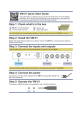
4 Connecting the VM-51 i Always switch off the power to each device before connecting it to your VM-51. After connecting your VM-51, connect its power and then switch on the power to each device. To connect the VM-51 as illustrated in the example in Figure 2: 1. Connect a composite video source (for example, a CV player) to the video INPUT BNC connector. 2. Connect up to 5 video output BNC connectors to the appropriate video acceptors (for example, CV displays). Not all outputs need to be connected. 3.
5 Technical Specifications INPUTS: 1 composite video, 1Vpp/75Ω on a BNC connector OUTPUTS: 5 composite video, 1Vpp/75Ω on BNC connectors MAX. OUTPUT LEVEL: 2.3Vpp /75Ω BANDWIDTH (-3dB): 360MHz DIFF. GAIN: 0.05% DIFF. PHASE: 0.07deg K-FACTOR: <0.05% S/N RATIO: 73dB CONTROLS: Level: -0.9 to +1.9dB, EQ.: 0 to +4.5dB @ 5.8MHz COUPLING: DC POWER CONSUMPTION: 12V DC, 80mA.
For the latest information on our products and a list of Kramer distributors, visit our Web site where updates to this user manual may be found. We welcome your questions, comments, and feedback. Web site: www.kramerelectronics.com E-mail: info@kramerel.