
User Manual

KRAMER: SIMPLE CREATIVE TECHNOLOGY
Using the VM-114H4C
12
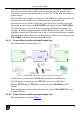
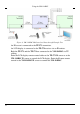
Figure 6: VM-114H4C IR Control and Pass-through Example Two
An IR sensor is connected to the TP-573 transmitter.
An LCD display is connected to the TP-574 receiver via an IR emitter.
Both the TP-573 and the TP-574 are connected to the VM-114H4C via TP
cabling.
Point the LCD display remote control either at the TP-573 IR sensor or at the
VM-114H4C IR sensor to control the LCD display. Point the Kramer remote
control at the VM-114H4C IR sensor to control the VM-114H4C.