Kramer Electronics, Ltd.
Contents Contents 1 2 2.1 2.2 3 3.1 3.2 3.3 4 5 5.1 5.2 Introduction Getting Started Recycling Kramer Products Quick Start Overview Using Shielded Twisted Pair Cable About the Power Connect™ Feature Recommendations for Best Performance Defining the VM-114H4C Using the VM-114H4C Connecting the VM-114H4C Acquiring the EDID 1 1 1 2 4 4 5 5 6 7 7 8 5.2.1 Disabling/Enabling Deep Color Support 5.3 5.4 Connecting to the VM-114H4C via RS-232 RS-232, IR Control and Pass-through 9 10 5.4.1 5.4.
Contents Tables Table 1: VM-114H4C Front Panel Features Table 2: VM-114H4C Rear Panel Features Table 3: Technical Specifications of the VM-114H4C Table 4: Default Communication Parameters Table 5: Protocol Definitions Table 6: Instruction Codes for Protocol 2000 ii 6 7 15 15 16 17 KRAMER: SIMPLE CREATIVE TECHNOLOGY
Introduction 1 Introduction Welcome to Kramer Electronics! Since 1981, Kramer Electronics has been providing a world of unique, creative, and affordable solutions to the vast range of problems that confront the video, audio, presentation, and broadcasting professional on a daily basis. In recent years, we have redesigned and upgraded most of our line, making the best even better! Our 1,000-plus different models now appear in 11 groups1 that are clearly defined by function.
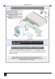
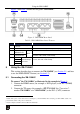
Getting Started Recycling Network (EARN) and will cover any costs of treatment, recycling and recovery of waste Kramer Electronics branded equipment on arrival at the EARN facility. For details of Kramer’s recycling arrangements in your particular country go to our recycling pages at http://www.kramerelectronics.com/support/recycling/. 2.2 Quick Start This quick start chart summarizes the basic setup and operation steps of the VM-114H4C.
Getting Started 3
Overview 3 Overview The high quality VM-114H4C is a switcher/distribution amplifier for HDMI and TP (Twisted Pair) signals. It reclocks and equalizes one of two selectable input signals and distributes it to four TP outputs. In particular, the VM-114H4C: • Supports up to 1.
Overview 3.2 About the Power Connect™ Feature The Power Connect™ feature here means that only the transmitter needs to be connected to a power source when the devices are within 90m (270ft) of each other. The Power Connect™ feature applies as long as the cable can carry power and the distance does not exceed 90m on standard CAT 5 cable. For longer distances, heavier gauge cable should be used1. ! 3.
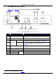
Defining the VM-114H4C 4 Defining the VM-114H4C Figure 1 and Table 1 define the front panel the VM-114H4C. Figure 1: VM-114H4C Front Panel Table 1: VM-114H4C Front Panel Features # 1 2 3 4 5 6 7 8 9 10 Feature IR Remote Control Sensor IR LED Function Sensor for the remote control IR transmitter Lights yellow when receiving signals from the IR remote control transmitter REMOTE IR 3.
Using the VM-114H4C Figure 2 and Table 2 define the rear panel VM-114H4C.
Using the VM-114H4C 3. Connect the TP RJ-45 outputs to up to four TP acceptors (for example, the PT-572+ Line Receiver1, the VM-114H or the VM-114H2C). 4. (Optional) Connect the front panel remote IR 3.5mm mini jack to the remote IR sensor. 5. (Optional) Connect a PC via RS-232 to the RS-232 port on the VM-114H4C (see Section 5.3). Figure 3: Connecting the VM-114H4C 5.2 Acquiring the EDID Each input on the VM-114H4C has a factory default EDID loaded2 (see Section 9).
Using the VM-114H4C • The default EDID (all output LEDs flash) • Up to four connected outputs using the Auto-mix Mode1 (all output LEDs light) To acquire the EDID: 1. Connect the output(s) from which you want to acquire the EDID. 2. Press the EDID SELECT button briefly. The last acquired EDID is indicated by the lit LED (for example, if Output LED 2 is lit, the EDID acquired was from Output 2). The device enters the EDID programming mode. 3.
Using the VM-114H4C To connect to the VM-114H4C via RS-232: • Connect the RS-232 9-pin D-sub rear panel port on the product unit via a 9-wire straight cable (only pin 2 to pin 2, pin 3 to pin 3, and pin 5 to pin 5 need to be connected) to the RS-232 9-pin D-sub port on your PC 5.4 RS-232, IR Control and Pass-through The VM-114H4C can be controlled via RS-232 and infrared.
Using the VM-114H4C When there is no IR sensor or emitter connected to the IR Remote 3.5mm mini jack, all signals received by the IR sensor on the front panel are passed to the transmitter and receiver bi-directionally over the CAT 5 cable allowing control of remote devices. When an IR sensor or emitter is connected to the IR Remote 3.
Using the VM-114H4C Figure 6: VM-114H4C IR Control and Pass-through Example Two An IR sensor is connected to the TP-573 transmitter. An LCD display is connected to the TP-574 receiver via an IR emitter. Both the TP-573 and the TP-574 are connected to the VM-114H4C via TP cabling. Point the LCD display remote control either at the TP-573 IR sensor or at the VM-114H4C IR sensor to control the LCD display. Point the Kramer remote control at the VM-114H4C IR sensor to control the VM-114H4C.
Using the VM-114H4C 5.4.2.3 IR Local Control and Pass-through Example Three The configuration is shown in Figure 7. Figure 7: VM-114H4C IR Control and Pass-through Example Three The first DVD player (player 1) is connected to the TP-573 transmitter via an IR emitter. The second DVD player (player 2) is connected to the VM-114H4C via an IR emitter. An IR sensor is connected to the TP-574 receiver. Both the TP-573 and the TP-574 are connected to the VM-114H4C via TP cabling.
Wiring the Twisted Pair RJ-45 Connectors 6 Wiring the Twisted Pair RJ-45 Connectors This section defines the TP pinout, using a straight pin-to-pin cable with RJ-45 connectors. i Note, that the cable Ground shielding must be connected/soldered to the connector shield.
Technical Specifications 7 Technical Specifications Table 3 lists the technical specifications1 of the VM-114H4C. Table 3: Technical Specifications of the VM-114H4C INPUTS: OUTPUTS: BANDWIDTH: COMPLIANCE WITH HDMI STANDARD: CONTROLS: INDICATOR LEDs: POWER CONSUMPTION: OPERATING TEMPERATURE: STORAGE TEMPERATURE: HUMIDITY: DIMENSIONS: WEIGHT: ACCESSORIES: OPTIONS: 8 1 HDMI Connector 1 TP on an RJ-45 Connector 4 TP on RJ-45 Connectors Supports up to 1.
Default EDID 9 Default EDID The factory default EDID is listed below. Monitor Model name............... VM114H4C Manufacturer............. KRM Plug and Play ID......... KRM0114 Serial number............ 505-707455010 Manufacture date......... 2009, ISO week 10 ------------------------EDID revision............ 1.3 Input signal type........ Digital Color bit depth.......... Undefined Display type............. RGB color Screen size.............. 520 x 320 mm (24.0 in) Power management.........
Kramer Protocol 2000 1st byte INPUT 1 I6 I5 I4 I3 I2 I1 I0 7 6 5 4 3 2 1 0 2nd byte OUTPUT 1 O6 O5 O4 O3 O2 O1 O0 7 6 5 4 3 2 1 0 1 OVR X M4 M3 M2 M1 M0 7 6 5 4 3 2 1 0 3rd byte MACHINE NUMBER 4th byte Bit 7 – Defined as 0. 1st BYTE: D – “DESTINATION”: 0 - for sending information to the switchers (from the PC); 1 - for sending to the PC (from the switcher).
Kramer Protocol 2000 INSTRUCTION DEFINITION FOR SPECIFIC INSTRUCTION # DESCRIPTION INPUT 62 DEFINE MACHINE 1 - number of inputs 2 - number of outputs NOTE OUTPUT 1 - for video 2 - for audio 14 NOTES on the above table: NOTE 2 - These are bi-directional definitions. That is, if the switcher receives the code, it will perform the instruction; and if the instruction is performed (due to a keystroke operation on the front panel), then these codes are sent.
For the latest information on our products and a list of Kramer distributors visit www.kramerelectronics.com where updates to this user manual may be found. We welcome your questions, comments and feedback. Safety Warning: Disconnect the unit from the power supply before opening/servicing. Caution P/N: 2900- 000645 Rev: 7 Kramer Electronics, Ltd. Web site: www.kramerelectronics.com E-mail: info@kramerel.