K R A ME R E LE CT R O N IC S L TD .
Contents 1 Introduction 1 2 2.1 2.2 2.3 3 3.1 3.2 3.3 4 4.1 Getting Started Achieving the Best Performance Safety Instructions Recycling Kramer Products Overview Using Twisted Pair Cable About the Power Connect™ Feature Defining the VM-114H2C Connecting the VM-114H2C Connecting to the VM-114H2C via RS-232 2 2 3 3 4 5 5 5 7 8 5 5.1 5.2 5.
1 Introduction Welcome to Kramer Electronics! Since 1981, Kramer Electronics has been providing a world of unique, creative, and affordable solutions to the vast range of problems that confront video, audio, presentation, and broadcasting professionals on a daily basis.
2 Getting Started We recommend that you: Unpack the equipment carefully and save the original box and packaging materials for possible future shipment Review the contents of this user manual i 2.1 Go to http://www.kramerelectronics.com/support/product_downloads.asp to check for up-to-date user manuals, application programs, and to check if firmware upgrades are available (where appropriate).
2.2 Safety Instructions ! 2.3 Caution: There are no operator serviceable parts inside the unit Warning: Use only the Kramer Electronics input power wall adapter that is provided with the unit Warning: Disconnect the power and unplug the unit from the wall before installing Recycling Kramer Products The Waste Electrical and Electronic Equipment (WEEE) Directive 2002/96/EC aims to reduce the amount of WEEE sent for disposal to landfill or incineration by requiring it to be collected and recycled.
3 Overview The VM-114H2C 2 Input 1:4 HDMI DA/2x CAT5 Outputs is a switcher/distribution amplifier for HDMI and TP (twisted pair) signals. It reclocks and equalizes one of two selectable input signals and distributes it to two HDMI and two TP outputs. In particular, the VM-114H2C features: A maximum data rate of 4.95Gbps (1.65Gbps per graphic channel), 6.75Gbps (2.
3.1 Using Twisted Pair Cable Kramer engineers have developed special twisted pair cables to best match our digital twisted pair products; the Kramer: BC-DGKat524 (CAT 5 24 AWG), the Kramer: BC-DGKat623 (CAT 6 23 AWG cable), and the Kramer: BC-DGKat7a23 (CAT 7a 23 AWG cable). These specially built cables significantly outperform regular CAT 5 / CAT 6 / CAT 7a cables. 3.
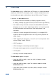
# Feature 1 IR Remote Control Sensor Sensor for the remote control IR transmitter 2 IR LED Lights yellow when receiving signals from the IR remote control transmitter 3 REMOTE IR 3.5mm Mini Jack 4 5 6 Function EDID Buttons Connect to a remote IR sensor READ Button Press (when one of the input LEDs is flashing to indicate a selected input) to read the selected EDID (see Section 5.1) SELECT Button Press repeatedly to cycle through the inputs to select an input from which to read the EDID.
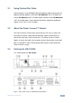
4 Connecting the VM-114H2C i Always switch off the power to each device before connecting it to your VM-114H2C. After connecting your VM-114H2C, connect its power and then switch on the power to each device. To connect the VM-114H2C as illustrated in the example in Figure 2: 1. Connect the HDMI source (for example, a DVD player) to the IN 1 (HDMI) connector. 2.
Figure 2: Connecting the VM-114H2C 2 Input 1:4 HDMI DA/2x CAT5 Outputs 4.1 Connecting to the VM-114H2C via RS-232 You can connect to the VM-114H2C via an RS-232 connection using, for example, a PC. Note that a null-modem adapter/connection is not required.
5 Operating the VM-114H2C This section describes how to use the VM-114H2C. 5.1 Acquiring the EDID Each input on the VM-114H2C has a factory default EDID loaded (see Section 9). This lets you connect the power before having to connect one of the acceptors. The VM-114H2C reads the EDID, which is stored in the non-volatile memory. You can acquire the EDID from: This is usually done only once, when the machine is being set up in an installation.
5.2 Disabling/Enabling Deep Color Support You can disable EDID deep color support to prevent signal deterioration when using long twisted pair cables on INPUT 2. To disable deep color and acquire EDID: 1. Disconnect the power. 2. Connect the output or outputs from which you want to acquire the EDID. 3. Connect the power while pressing the EDID READ button. 4. Perform steps 3 and 4 in Section 5.1. To enable deep color and acquire EDID: 1. Disconnect the power. 2.
5.3.1 RS-232 Control and Pass-Through Using the VM-114H2C As shown in Figure 3, you can connect a PC (or other serial controller) directly to the VM-114H2C to control the VM-114H2C. The VM-114H2C also transparently passes bidirectional RS-232 signals over the TP cable from the TP-573 transmitter to the TP-574 receiver. For example, a PC connected to the RS-232 port on the TP-573 can control an RS-232-controllable device (for example, a projection screen) connected to the TP-574.
When an IR sensor or emitter is connected to the IR remote 3.5mm mini jack, the connection between the IR sensor on the front panel and the IR on the transmitter/receiver is broken so that any signal received by the IR sensor on the front panel remains local to the VM-114H2C and controls only the VM-114H2C.
5.3.4 IR Local Control and Pass-Through Example 2 The configuration is shown in Figure 5. Figure 5: VM-114H2C IR Control and Pass-Through Example 2 An IR sensor is connected to the TP-573 transmitter. An LCD display is connected to the TP-574 receiver via an IR emitter. Both the TP-573 and the TP-574 are connected to the VM-114H2C via TP cabling. Point the LCD display remote control either at the TP-573 IR sensor or at the VM-114H2C IR sensor to control the LCD display.
5.3.5 IR Local Control and Pass-Through Example 3 The configuration is shown in Figure 6. Figure 6: VM-114H2C IR Control and Pass-Through Example 3 The first DVD player (player 1) is connected to the TP-573 transmitter via an IR emitter. The second DVD player (player 2) is connected to the VM-114H2C via an IR emitter. An IR sensor is connected to the TP-574 receiver. Both the TP-573 and the TP-574 are connected to the VM-114H2C via TP cabling.
6 Wiring the Twisted Pair RJ-45 Connectors When using STP cable, connect/solder the cable shield to the RJ-45 connector shield. Figure 7 defines the TP pinout using a straight pin-to-pin cable with RJ-45 connectors. i Note, you must connect/solder the cable ground shielding to the connector shield.
7 Technical Specifications INPUTS: 1 HDMI connector 1 twisted pair on an RJ-45 connector OUTPUTS: 2 HDMI connectors 2 twisted pair on RJ-45 connectors MAX.DATA RATE: 6.75 ( 2.25Gbps per graphic channel, HDMI), 4.95Gbps (1.
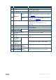
8 Default Communication Parameters The following table lists the default communication parameters for the VM-114H2C.
9 Default EDID The factory default EDID is listed below. Monitor Model name Manufacturer Plug and Play ID Serial number Manufacture date ------------------------EDID revision Input signal type Color bit depth Display type Screen size Power management Extension blocs ------------------------DDC/CI Color characteristics Default color space Display gamma Red chromaticity Green chromaticity Blue chromaticity White point (default Additional descriptors VM114H2C KRM KRM0114 505-707455010 2009, ISO week 10 1.
10 Protocol 2000 This RS-232/RS-485 communication protocol uses four bytes of information as defined below. For RS-232, a null-modem connection between the machine and controller is used. The default data rate is 9600 baud, with no parity, 8 data bits and 1 stop bit. Note: Compatibility with Kramer’s Protocol 2000 does not mean that a machine uses all of the commands below. Each machine uses a sub-set of Protocol 2000, according to its needs. 10.
Instruction Codes for Protocol 2000 Instruction Definition for Specific Instruction # Description Input Output 1 SWITCH VIDEO 61 IDENTIFY MACHINE Set equal to video input that is switched (0 = disconnect) 1 – Video machine name 2 – Audio machine name 3 – Video software version 4 – Audio software version 5 – RS-422 controller name 6 – RS-422 controller version 7 – Remote control name 8 – Remote software version 9 – Protocol 2000 revision 10 – Control data machine name 11 – Control data software ver
For the latest information on our products and a list of Kramer distributors, visit our Web site where updates to this user manual may be found. We welcome your questions, comments, and feedback. Web site: www.kramerelectronics.com E-mail: info@kramerel.