KRAMER E le c tro n ic s MATRIX ROUTING SWITCHER 1
KRAMER E le c tro n ic s MATRIX ROUTING SWITCHER 2
KRAMER E le c tro n ic s MATRIX ROUTING SWITCHER TABLE OF CONTENTS 1 HARDWARE ........................................................................................................................................ 4 1.1 GENERALITIES .......................................................................................................................................... 4 1.2 RACK DISPOSITION.....................................................................................................................
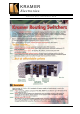
KRAMER E le c tro n ic s MATRIX ROUTING SWITCHER 1 HARDWARE 1.1 GENERALITIES The Kramer matrix switchers are used to select and dispatch electric signals, as audio, vidéo and RGB, to several destination simultaneously. The impedances of each machine which is connected on the matrix are well respected, even if a signal goes to two outputs and more. As a matter of fact, a signal under 75 Ohms can’t be delivered on several loads without any amplification dispositive.
KRAMER E le c tro n ic s MATRIX ROUTING SWITCHER Kramer output cards (called BMS), own a 41612 DIN connector to get the power supply and the service signals by the internal rail. Each cars has 8 BNC connectors for in or out. 1.3 CREATING A MATRIX The rear panel of the rack is 84 E wide, on 3RU high. (E=5,08 mm). The mains, RS232 and RS422 plugs 12 E. So, the useful area for the audio, vidéo et RGB is 72 E. The BNC are shared by four, on vertical bands which are 2,5 E wide, on 3RU.
KRAMER E le c tro n ic s MATRIX ROUTING SWITCHER this bus transit the stereo audio signals, and also the power distribution and the service signals. The cards are normalized at Euro 100x220 mm, and can be extracted by the rear panel. Each card own up to eight stereo plugs. There is two types of audio cards : - Input audio cards. Called WME, these cards are idendicals beetween themselves. The only differences are the serigraphy of the panel and its position in the slots.
KRAMER E le c tro n ic s MATRIX ROUTING SWITCHER 2 COMMUNICATION PROTOCOL “MX06” INCLUDING OPTIONS (02/09/2005 VER-5.06) This RS-232 / RS-485 communication protocol uses four bytes of information as defined below. For RS-232, a null-modem connection between the machine and controller is used. The default data rate is 9600 baud, with no parity, 8 data bits and 1 stop bit.
KRAMER E le c tro n ic s MATRIX ROUTING SWITCHER 2nd BYTE: Bit 7 – Defined as 1. D6…D0 – “INPUT or DATA”. When switching (ie. instruction codes 1 and 2), the INPUT (MSB + 7 bits) is set as the input number which is to be switched. For other operations, these bits are defined according to the table. 3rd BYTE: Bit 7 – Defined as 1. A6…A0 – “OUTPUT or ADRESS”. When switching (ie. instruction codes 1 and 2), the OUTPUT (7 bits) is set as the output number which is to be switched.
KRAMER E le c tro n ic s MATRIX ROUTING SWITCHER 13h 19 53h 83 STORE STATUS Set as SETUP#(0-7) 14h 20 55h 84 RECALL STATUS 15h 21 55h 85 SET AUDIO Output VCA Set as SETUP#(0-7) Equal to output number whose VCA is to be set (0 = all) 16h 22 56h 86 SET AUDIO GAIN and Balanced or Unbalanced mode for audio input Equal to input number whose gain or bal/unbal mode is to be set (0 = all) 19h 25 55h 85 REQUEST Audio output VCA Equal to output number whose gain is requested 19h 25 56h
KRAMER E le c tro n ic s MATRIX ROUTING SWITCHER replies to instructions 10 and 11 are as per the definitions in instructions 7 and 8 respectively. For example, if the present status of machine number 5 is breakaway setting, then the reply to the HEX code 0Bh 80h 80h 85h would be 4Bh 80h 81h 85h NOTE 3 - An error code is returned to the PC if an invalid instruction code was sent to the switcher, or if a parameter associated with the instruction is out of range (e.g.
KRAMER E le c tro n ic s MATRIX ROUTING SWITCHER NOTE 10 – POWER ON RESET. The output register has a value under the binar form : 1 0 POR1 POR0 P3 P2 P1 P0 P3…P0 : vca slope from 0 to 9 seconds POR1 = 0 : POR0 = 0 : vca max when power on. POR0 = 1 : vca min when power on. POR1 = 1 : recall vca when power on. NOTE 11 – REFRESH the ON SCEEN DISPLAY. The GMOSD card will be restarted to be refreshed.
KRAMER E le c tro n ic s MATRIX ROUTING SWITCHER 3 MATRIX HOOK-UP 3.1 MAINS AND GROUND ISOLATION The electric ground of all the plugs are the same, but isolated from the rack. The rack is directly grounded by the mains cable. 3.2 VIDEO Video inputs and outputs are standards plugs BNC 75 Ohms. BNC BNC Electric equivalent plan : 3.3 RGBhv RGBHV inputs and outputs are standard plugs : BNC. R,G, and B signals are analogs under 75 Ohms. Level = 1V H and V are logicals under 1 Kohms.
KRAMER E le c tro n ic s MATRIX ROUTING SWITCHER 3.4 AUDIO Audio inputs and outputs are terminal blocks 3 points detachable: 3.4.1 BALANCED INPUTS 3.4.3 BALANCED OUTPUTS XLR : XLR : Ground Hot Point Cold Point 1- Ground 2- Hot 3- Cold 1- Ground 2- Hot 3- Cold Ground Hot Point Cold Point 3.4.4 UNBALANCED OUTPUTS RCA : 1- Ground 2- Hot 3- Cold Ground Signal –10dB Importante Note: DO NOT CONNECT SKEWER 3 TO THE GROUND (audio signal always présent on this line). 3.4.
KRAMER E le c tro n ic s MATRIX ROUTING SWITCHER 4 GENERAL FEATURES - Output Level: 4V - Jitter max: 20nS 4.1 VIDEO SECTION - Bandwidth @ -3dB: 325 Mhz - Crosstalk @ 4,43 Mhzes: -60 dB between two adjacent lines. -75 dB between two extreme lines. - Differential gain: < 0,5% max. - Differential phase < 0,5° max.
KRAMER E le c tro n ic s MATRIX ROUTING SWITCHER 5 TOUCH KEYBOARD : LUMINOUS RE-LABELABLE 5.1 PRESENTATION The keyboard permits the remote control of the switching matrix, without the use of a PC station. It is housed in 19" 1‘U’cabinet, with 8, 16, 24 or 32 selection, or in a built-in box. The selected key is illuminated. Each of the keys can be re-labelled, by writing in the name of the source or the destination. This keyboard is auto - powered by the matrix, via the RS422 connector.
KRAMER E le c tro n ic s MATRIX ROUTING SWITCHER 6 INCREMENTAL TOUCH KEYBOARD AND LCD DISPLAY 6.1 PRESENTATION 6.4 WORKING This keyboard permits the remote control of the switching matrix, without the use of a PC station. It is housed in a 19 inch 1U cabinet, with 2 keys for selection of the inputs, 2 keys of selection for the outputs, and a validation key. The configuration status of the switch actions selected is shown on the LCD display.
KRAMER E le c tro n ic s MATRIX ROUTING SWITCHER 7 MATRIX_OP4 SOFTWARE 7.1 INTRODUCTION 7.2 Glossary : The principle of the routing switcher is to connect each of its outputs to any or all of the inputs. Therefore the possible points of switching is a multiple of the number of inputs and the number of outputs. This principle is best described in the listview form. This grid is composed of switching points, and of distributors. (For instance Input 1 can be selected to go to Outputs 6,7 and 8.
KRAMER E le c tro n ic s MATRIX ROUTING SWITCHER A matris routing switcher can contain many differents layers, according to the kind of electric signals : Composite Video layer Analog Audio (mono or stéréo) layer S-Video (or YC) layer YUV layer RGB or RGBS or RGBHV layer AES-EBU (Digital Audio) layer SDI (Digital Vidéo) layer 5) Check if there is evidence of connection between the devices declared in the menus and the real configurations of the matrix.
KRAMER E le c tro n ic s MATRIX ROUTING SWITCHER Four layers can work simultaneously, and each one can have a different size. 7.5 MATRIX CONTROLLER 7.5.1 General Informations 7.4.1.1 Names and Connectors capture. Click on the box of a source or destination object. This window opens : The mains routine of the software Matrix_Op4 consist to create some crosspoints beetween various sources and destinations.
KRAMER E le c tro n ic s MATRIX ROUTING SWITCHER If the mouse is connected on the COM 1, you cannot use the link RS 232 on COM1 for the matrix. Use another COM port (See page 18 setup). In this window, choose in the layers that you want use, or in the all list, the sources you want. The switching will be automatically installed featuring the disponibilities. 7.6 COPY BACK-UP When the edition of the menu is finished, it is important to make a copy on a diskette.
KRAMER E le c tro n ic s MATRIX ROUTING SWITCHER 21
KRAMER E le c tro n ic s MATRIX ROUTING SWITCHER 22