
Manual
5
KRAMER
Electronics
MATRIX ROUTING SWITCHER
2 COMMUNICATION
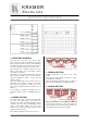
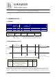
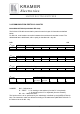
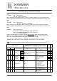
2.1 FORMAT
Interface
Speed
(Bauds)
DAT
A
(Bits)
Parity STOP
(bits)
RxD level TxD level
RS232 9600 8 no Min. :1 Max. : 5 Min. :+/-4v Max. :+/-12v +/-10v
RS422 9600 8 no Min. :1 Max. : 5 Min. :0v Max. :+5v 0v / +4v
KEYBOARD 9600 8 no Min. :1 Max. : 5 Min. :0v Max. :+5v 0v / +4v
Octet Octet 2 Octet 3 Octet 4 Octet 5
1 2 3 4
FORMAT OF
THE DATA
Instruction Input / Data Output / Address Layer
NOTES: Input / Data : Hexadecimal number of source (00h to EFh)
Output / Address : Hexadecimal number of destination (00h to EFh)
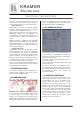
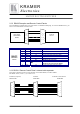
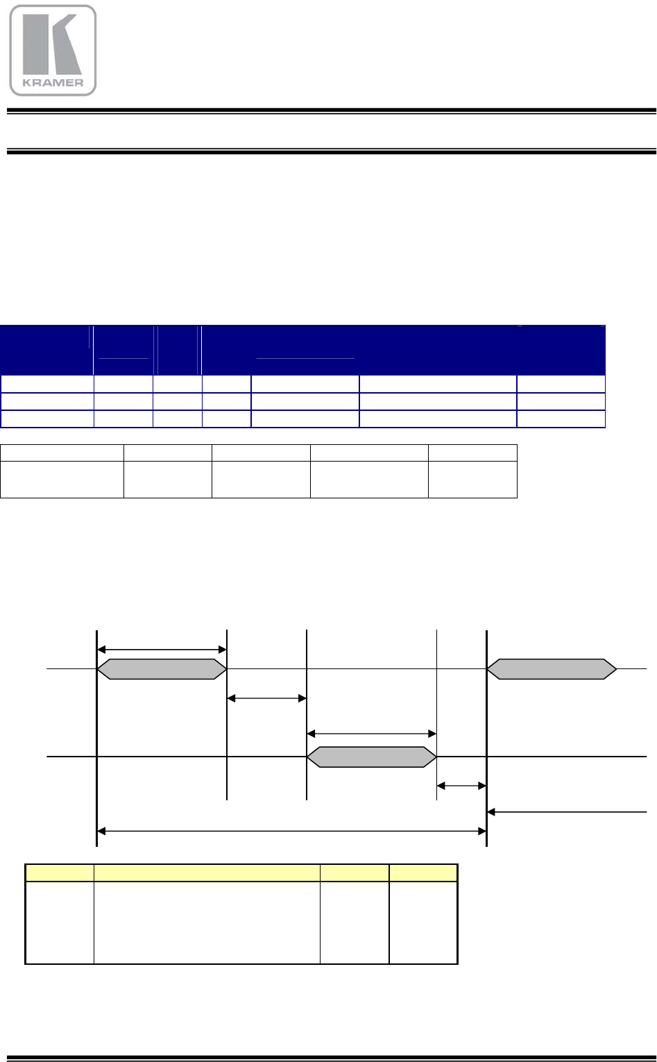
2.2 TRANSMISSION CYCLE
Symbol Description Time Units
Trec Command reception 4 mS
Twr Working time of the Matrix 15 mS
Tret Return Informations from the Matrix 4 mS
Ts Time for ready 2 mS
Tmc Maximum time of a cycle 25 mS
EXPLANATION : Reception time RX is 4 milli-Seconds. The routing switcher operates during 15 mS, returns
the answer TX (4 mS), and comes back to ready state after 2 mS. The routing switcher takes 25 milli-Seconds to
execute a command. When a new command occurs during unready time (Tmc), this command will be
RX
Command from
the computer
TX
(matrix return)
Twr
Trec
Ts
Tmc
Next command
Tret