Kramer Electronics, Ltd.
Contents Contents 1 2 2.1 3 4 5 6 6.1 6.2 7 7.1 7.
Introduction 1 Introduction Welcome to Kramer Electronics! Since 1981, Kramer Electronics has been providing a world of unique, creative, and affordable solutions to the vast range of problems that confront the video, audio, presentation, and broadcasting professional on a daily basis. In recent years, we have redesigned and upgraded most of our line, making the best even better! Our 1,000-plus different models now appear in 11 groups 1 that are clearly defined by function.
Getting Started 2.1 Quick Start This quick start chart summarizes the basic setup and operation steps.
Overview 3 Overview The SP-11D is a multi-standard / multi-format, broadcast quality video processor – ProcAmp, TBC, format converter (for mixing different types of equipment), and standards converter. It is a universal single-box solution for all your video processing requirements.
Your SP-11D Digital Video Processor To achieve the best performance: • Use only good quality connection cables 1 to avoid interference, deterioration in signal quality due to poor matching, and elevated noise levels (often associated with low quality cables).
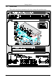
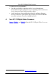
Your SP-11D Digital Video Processor Figure 1: SP-11D Digital Video Processor 5
Your SP-11D Digital Video Processor Table 1: Front Panel SP-11D Digital Video Processor # Feature 1 POWER Switch 2 INPUT STANDARD LEDs Function Illuminated switch for turning the unit ON or OFF Cycle between PAL B, PAL N, PAL M, NTSC 3, NTSC 4, and SECAM. The corresponding LED lights 3 INPUT Selector Button Press to select the source, illuminating the appropriate LED 4 INPUT LEDs Cycle between the video sources: CV, YC, YUV, and RGB/S.
Your SP-11D Digital Video Processor # Feature 25 V/RED Button 26 YUV/RGB LEDs 27 COLOR SPACE Button 28 29 30 31 32 33 34 STORE Button RECALL Button 7-segment Display - Button + Button FREEZE Button PANEL LOCK Button Function 4 5 6 Press the V /RED button and adjust using the + and – buttons Cycle between the different color spaces of color control: YUV and RGB.
Installing on a Rack 5 Installing on a Rack This section provides instructions for rack mounting the 1U unit.
Connecting Your SP-11D Digital Video Processor 6 Connecting Your SP-11D Digital Video Processor You can use your SP-11D to convert composite video, s-Video, component video (YUV or RGB/S), or SDI signals to composite video, s-Video, component video (YUV, RGsB, RGBS, RGBHV) and 1 SDI. The processing can be evaluated on a “Before/after” split-screen, as the example in Figure 4 illustrates. To connect the SP-11D Digital Video Processor, do the following 2: 1.
Connecting Your SP-11D Digital Video Processor 6.1 Connecting a PC You can connect to the unit via a crossed RS-232 connection, using for example, a PC. A crossed cable or null-modem is required as shown in method A and B respectively. If a shielded cable is used, connect the shield to pin 5. Method A (Figure 2)—Connect the RS-232 9-pin D-sub port on the unit via a crossed cable (pin 2 to pin 3, pin 3 to pin 2, and pin 5 to pin 5) to the RS-232 9-pin D-sub port on the PC.
Connecting Your SP-11D Digital Video Processor 6.2 DIP-Switch Settings The SP-11D DIP-switch settings are defined in Table 3 and Table 4: Table 3: DIP-switch Settings DIP-Switch Pedestal 1 Set as follows: ON for pedestal of output signal (7.
Operating the SP-11D Digital Video Processor Figure 4: Connecting the SP-11D Digital Video Processor 7 Operating the SP-11D Digital Video Processor Operate your SP-11D Digital Video Processor via: • The front panel buttons • RS-232 serial commands transmitted by a touch screen system, PC, or other serial controller To operate the SP-11D using the front panel buttons, do the following: 1.
Operating the SP-11D Digital Video Processor 2. When the AUTO button illuminates, the video standard corresponding to the selected input is detected automatically. The appropriate INPUT STANDARD LED lights: PAL B, PAL N, PAL M, NTSC 3.58, NTSC 4.43 or SECAM 1. When the AUTO button does not illuminate—that is, the SP-11D is in manual mode—select the desired video standard by pressing the AUTO button to cycle between the various video standards. 3.
Operating the SP-11D Digital Video Processor Press the + button or – button once to gradually increase or decrease the current level by one unit (the 7-segment display shows the new level) To increase or decrease the current level rapidly, press and hold down the + button or – button, continuously 1. To end the rapid adjustment, release the + button or – button Note, if you want to: • Set the normal level (“NORM”) of the current level, press and simultaneously hold down both the + button and – button.
Operating the SP-11D Digital Video Processor 7.2 Locking the Front Panel To prevent changing the settings unintentionally or tampering with the front panel, lock your SP-11D. Unlocking releases the protection mechanism. To lock the SP-11D: • Press the PANEL LOCK button (for about 2 seconds) until it illuminates — freezing the front panel controls.
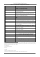
Technical Specifications 8 Technical Specifications Table 5 includes the technical specifications: 1 Table 5: Technical Specifications of the SP-11D Digital Video Processor INPUTS: OUTPUTS: 1 composite video: 1Vpp/75Ω on a BNC connector; 1 Y/C: 1Vpp/75Ω (Y), 0.3Vpp/75Ω (C) on a 4‑pin connector; 1 component: Y/R‑Y/B‑Y (or RGB/S) 1Vpp/0.7Vpp/0.7Vpp/75Ω on BNC connectors; 1 SYNC (genlock): looped 75Ω/Hi‑Z on BNC connectors; 1 SDI: SMPTE-259M, ITU-R BT.
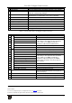
Communication Protocol 9 Communication Protocol This protocol, which enables RS-232 communication between the SP-11D and the PC, uses 4 bytes of information, and data is at 9600 baud. Table 6: Protocol Definitions First byte options DEC HEX 1 128 80 2 160 A0 3 161 A1 4 162 A2 5 163 A3 6 189 BD 7 33 21 Second byte is the command type Third byte is the parameter value RESET VIDEO READ PARAMETER WRITE PARAMETER RECALL STORE IDENTIFY MACHINE Set (for the rest of commands) Note: 1.
Communication Protocol 20 GLOBAL OUTPUT FORMAT 21 OUTPUT_STANDARD 22 GENLOCK 23 PANEL_LOCK 24 24 26 SCH DELAY FREEZE 27 28 PROGRAM GENLOCK_STAT 0 - YUV 1 - RGB 2 - RGBS 0 - PAL B 1 - PAL N 2 - PAL M 3 - NT 3 4 - NT 4 5 - SEC 0 - OFF 1 - ON 0 - OFF 1 – ON -100 - +100 -100 - +100 0 - OFF 1 - ON 0 - 15 (read only) (Read only) 0 – No GENLOCK 1 – GENLOCK Byte 4 is the machine address: can be 98 or 99 (in HEX).
Communication Protocol STORE PC -> I = 35;D = 0;E = PROGRAMM NUMBER -> MACHINE PC <- I = 34;D = 0;E = PROGRAMM NUMBER <- MACHINE (RECALL) IDENTIFY MACHINE MACHINE NAME PC -> I = 61;D = 1;E = 0 -> MACHINE PC <- I = 61;D = MACHINE NAME HIGH;E = MACHINE NAME LOW <- MACHINE SOFTWARE VERSION PC -> I = 61;D = 3;E = 0 -> MACHINE PC <- I = 61;D = SOFTWARE VERSION HIGH;E = SOFTWARE VERSION LOW <- MACHINE Examples: 1. Select CV input format: H21 H80 H80 H98 Unit response: H61 H80 H80 H98 2. Reset: H80 H80 H80 H98 3.
LIMITED WARRANTY Kramer Electronics (hereafter Kramer) warrants this product free from defects in material and workmanship under the following terms. HOW LONG IS THE WARRANTY Labor and parts are warranted for seven years from the date of the first customer purchase. WHO IS PROTECTED? Only the first purchase customer may enforce this warranty. WHAT IS COVERED AND WHAT IS NOT COVERED Except as below, this warranty covers all defects in material or workmanship in this product.
For the latest information on our products and a list of Kramer distributors, visit our Web site: www.kramerelectronics.com, where updates to this user manual may be found. We welcome your questions, comments and feedback. Safety Warning: Disconnect the unit from the power supply before opening/servicing. Caution Kramer Electronics, Ltd. Web site: www.kramerelectronics.com E-mail: info@kramerel.