Kramer Electronics, Ltd.
Contents Contents 1 2 3 4 5 5.1 5.2 5.3 6 7 7.1 7.2 Introduction Getting Started Overview Your RC-IR2 Remote Control Transmitter Your Remote Receiver Identifying the Built-in Infrared Receiver Connecting the External Infrared Receiver Using the RC-IR2 Remote Control Transmitter The General (Gray) Keys The Router Mode Keys Configuration Initializing the RC-IR2 1 1 2 3 5 5 5 7 7 8 8 9 7.2.1 7.2.2 Assigning the ROUTER Number Assigning the GROUP Number 9 9 7.
Contents Figures Figure 1: RC-IR2 Remote Control Transmitter Figure 2: Built-in Remote Receiver Figure 3: Connecting the External Remote Receiver Figure 4: VP-23N Switcher Selector Buttons Figure 5: VP-26 Switcher Selector Buttons 3 5 6 14 16 Tables Table 1: RC-IR2 Remote Control Transmitter Features Table 2: RC-IR2 Initializing Sequence Table 3: Group Definition Specifications for Older Machines Table 4: Group Definition Criteria for Older Machines Table 5: Groups Definitions for the VP-23N / VP-23RC Ta
Introduction 1 Introduction Welcome to Kramer Electronics! Since 1981, Kramer Electronics has been providing a world of unique, creative, and affordable solutions to the vast range of problems that confront the video, audio, presentation, and broadcasting professional on a daily basis. In recent years, we have redesigned and upgraded most of our line, making the best even better! Our 1,000-plus different models now appear in 11 groups1 that are clearly defined by function.
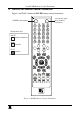
Overview 3 Overview The high performance Kramer RC-IR2 is an upgrade of the popular RC-IR1, with additional functionality that lets you control Kramer scalers as well as switchers. The RC-IR2: Is a hand held infrared remote control transmitter1 that includes the protocols of all Kramer devices and is programmable to control any Kramer machine (see Figure 1) Transmits to a compatible remote receiver, either built-in (see Figure 2) or external (see Figure 3).
Your RC-IR2 Remote Control Transmitter 4 Your RC-IR2 Remote Control Transmitter Figure 1 and Table 1 define the RC-IR2 remote control transmitter: POWER:Cycles power The red LED lights when sending instructions Button colors key: WHITE Routers/Switchers GRAY General BLUE Scalers Figure 1: RC-IR2 Remote Control Transmitter 3
Your RC-IR2 Remote Control Transmitter Table 1: RC-IR2 Remote Control Transmitter Features Keys Selector ROUTER Mode Buttons SCALER Source Mode Selector FREEZE OUT STO RCL - Single Digit Mode -- Double Digit Mode GROUP LOCK Auto Image Auto Gain MODE SCALE Navigation Control (5 keys) PIP SWAP BRIGHT CONT VOLVOL+ ROUTER SCALER MENU ALL OFF ESC TAKE VIDEO AUDIO AFV Function 20 buttons for selecting the channels, the group, the machine number, machine type and so on (see section 7) 18 source selector keys:
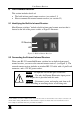
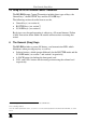
Your Remote Receiver 5 Your Remote Receiver This section includes details of: The built-in front panel remote receiver (see section 5.1) How to connect the external remote receiver (see section 5.2) 5.1 Identifying the Built-in Infrared Receiver Most Kramer switchers1 include a built-in front panel remote receiver that is located to the left of the power switch, as Figure 2 illustrates: IR Receiver LED Figure 2: Built-in Remote Receiver 5.
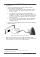
Your Remote Receiver To connect the external remote receiver, as the example in Figure 3 illustrates, do the following: 1.
The General (Gray) Keys 5.3 Using the RC-IR2 Remote Control Transmitter The RC-IR2 Remote Control Transmitter includes three types of keys: the General keys1, the ROUTER2 keys and the SCALER keys. The following sections describe how to use the: General keys (see section 6) ROUTER keys (see section 7) SCALER keys (see section 8) By design, every keypad operation is subject to a 10 second timeout. Failure to fully execute an action within 10 seconds will necessitate restarting that action.
The Router Mode Keys 7 The Router Mode Keys This section describes how to: Configure the RC-IR2 (see section 7.1) Initialize the RC-IR2 (see section 7.2) Use the ROUTER Mode keys (see section 7.3) 7.1 Configuration For the RC-IR2 to identify the switcher that it has to control, a ROUTER number (see section 7.2.1) and a GROUP number1 (see section 7.2.2) need to be assigned for specific identification of each switcher.
The Router Mode Keys 7.2 Initializing the RC-IR2 Table 2 describes the initializing sequence: Table 2: RC-IR2 Initializing Sequence Press To IR LED Behavior on the Switcher Front Panel See Section <-> Select single digit ON and then OFF 7.3.1 ROUTER 1 or other Select the machine number Set the machine number ON OFF 7.2.1 7.2.
The Router Mode Keys Table 2 defines the allocation of machines to groups, and Table 4 defines the group criteria: Table 3: Group Definition Specifications for Older Machines Group 1 Products SD-7308; VP-61xl/N; 2031n; VS-401, VS-601, VS-801; VS-401N, VS-601N, VS-801N Group 2 Products VS-402, VS-602, VS-802, VS-1202 (BUS A) Group 3 Products VS-402, VS-602, VS-802, VS-1202 (BUS B) Group 4 Products 2081; VS-2481, 2016; VS-2053 Group 51 Products VS-4x4YC Group 61 Products VS-5x4 Group 7 Products
The Router Mode Keys Table 2 is valid as per January 2004. Newer machines (using Protocol 2000) may be programmed for Group 12 or 11. Table 4: Group Definition Criteria for Older Machines Speed1 Group 1, 2, and 3 4, 5, 6, 7, 9, 10 12, 14, 15, 16, 17, 18 and 20 Group 1200 9600 Maximum # of Units per Group 2 Groups 7 , 9 and 10 1 Groups 1, 2, 3, 5, 6, 15, 17, and 18 Groups 4, 12, 14, and 16 8 16 7.
The Router Mode Keys 7.3.2 Switching an Input to an Output To switch an input to an output after assigning the machine number and group number, do the following: 1. Press a Selector key number for the output1. 2. Press a Selector key number for the input. For example, to switch INPUT 3 to OUTPUT 5 on a switcher, press <5> and then <3> (in the single digit mode). In the double-digit mode, press the <--> key and then <0/10>, <5> and <0/10>, <3>. 7.3.
The Router Mode Keys 7.3.4 The TAKE Key You can use the TAKE key to key-in several actions and then confirm them by pressing the TAKE key, to simultaneously activate the multiple switches. Otherwise: OUT-IN combinations can be executed one at a time Pressing an OUT-IN combination implements the switch immediately No protection is offered to allow the correction of an erroneous action before it is implemented The TAKE key on RC-IR2 can be used regardless of the state of the TAKE button on the switcher. 7.
The Router Mode Keys 7.4 Controlling a Presentation Switcher This section describes how to control Presentation Switchers using the RC-IR2. To control the: VP-23N and the VP-23RC, see section 7.4.1 VP-26, see section 7.4.2 7.4.1 1 Controlling the VP-23N via the RC-IR2 You can control the VP-23N Presentation Switcher using the RC-IR2 to do the following: Switch inputs to outputs (see section 7.4.1.1) Adjust the volume (see section 7.4.1.2) 7.4.1.
The Router Mode Keys To switch an input to an output, point the remote control transmitter at the remote receiver and do the following: 1. Press the VIDEO key. 2. Press the group number1 and then press any key from <1> to <4> to switch an input to the output. For example, to switch input 3 in the s-Video group to the output: Press the VIDEO key Press 2 Press 3 To switch the master audio switcher, point the remote control transmitter at the remote receiver and do the following: 1. Press the AUDIO key. 2.
The Router Mode Keys Table 6: Audio Output Type Key for the VP-23N/VP-23RC Press key: To adjust the audio level of the: 1 2 3 4 5 CV group s-Video group VGA group Microphone Master audio out Decreasing the Volume of the VP-23N To increase the volume, point the remote control transmitter at the remote receiver and do the following: 1. Press the VOL- key. 2. Press the numeral key defining the audio signal3 continuously until the volume decrease is satisfactory. 7.4.
The Router Mode Keys Table 7: Groups Definitions for the VP-26 The Switcher Group Is defined as: VGA/UXGA 1 Video (CV) 1 s-Video (Y/C) 1 Comp 1 VGA/UXGA 2 Video (CV) 2 s-Video (Y/C) 2 Comp 2 1 2 3 4 5 6 7 8 To switch an input to an output, point the remote control transmitter at the remote receiver and do the following: 1. Press the VIDEO key. 2. Press the group number1 and then press any key from <1> to <4>2 to switch an input to the output .
The Router Mode Keys To increase the volume, point the remote control transmitter at the remote receiver and do the following: 1. Press the VOL+ key. 2. Press the numeral key defining the audio signal1 continuously until the volume increase is satisfactory.
Operating in the Scaler Mode 8 Operating in the Scaler Mode The RC-IR2 includes the main1 SCALER functions; other functions can only be accessed via the OSD menu keys. To recognize a Kramer machine when operating in the Scaler Mode, using the RC-IR2, point the remote control transmitter at the remote receiver and do the following: 1. Press the SCALER key. 2.
LIMITED WARRANTY Kramer Electronics (hereafter Kramer) warrants this product free from defects in material and workmanship under the following terms. HOW LONG IS THE WARRANTY Labor and parts are warranted for seven years from the date of the first customer purchase. WHO IS PROTECTED? Only the first purchase customer may enforce this warranty. WHAT IS COVERED AND WHAT IS NOT COVERED Except as below, this warranty covers all defects in material or workmanship in this product.
For the latest information on our products and a list of Kramer distributors, visit our Web site: www.kramerelectronics.com, where updates to this user manual may be found. We welcome your questions, comments and feedback. Safety Warning: Disconnect the unit from the power supply before opening/servicing. Caution Kramer Electronics, Ltd. Web site: www.kramerelectronics.com E-mail: info@kramerel.