Kramer Electronics, Ltd.
Contents Contents 1 2 3 4 4.1 4.2 4.3 5 5.1 5.2 5.3 6 6.1 6.2 6.
Introduction 1 Introduction Welcome to Kramer Electronics! Since 1981, Kramer Electronics has been providing a world of unique, creative, and affordable solutions to the vast range of problems that confront the video, audio, presentation, and broadcasting professional on a daily basis. In recent years, we have redesigned and upgraded most of our line, making the best even better! Our 1,000-plus different models now appear in 11 groups1 that are clearly defined by function.
Getting Started 2 Getting Started We recommend that you: Review the contents of this user manual Use Kramer high performance high resolution cables1 2 A special CONFIG cable is required to configure and perform firmware upgrades to the machine 3 Overview The RC-7LC / RC-7LCE is a highly versatile controller interface panel for the control of A/V equipment in any multimedia room, especially the control of a projector or other display device, via RS-232 and/or IR emitter cable.
Overview To achieve the best performance: Connect only good quality connection cables, thus avoiding interference, deterioration in signal quality due to poor matching, and elevated noise- levels (often associated with low quality cables) Avoid interference from neighboring electrical appliances and position the RC-7LC / RC-7LCE away from moisture, excessive sunlight and dust Caution – No operator-serviceable parts inside unit.
Your RC-7LC / RC-7LCE 4 Your RC-7LC / RC-7LCE This section defines the: Front panel of the RC-7LC (see section 4.1) Front panel of the RC-7LCE (see section 4.2) Side panel of the RC-7LC and RC-7LCE (see section 4.3) 4.
Your RC-7LC / RC-7LCE 4.
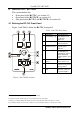
Your RC-7LC / RC-7LCE 4.3 Defining the RC-7LC / RC-7LCE Side Panel Figure 3 illustrates an enlarged view of the side panel of the RC-7LC and RC-7LCE: Figure 3: Side Panel of the RC-7LC and RC-7LCE (Enlarged View) Figure 4 defines the side panel of the RC-7LC and RC-7LCE. For an explanation of how to install and configure, refer to the chapter entitled: Installation of the RC System in the online RC Configuration and Installation guide1. 1 Download it from http://www.kramerelectronics.
Your RC-7LC / RC-7LCE & 1(2 % ) 3% % #'45+6 2% 2 % 2 % . ) / )% . ( ).% % 0 ,! &' 386,!54& . / 2 '* !+ ',,) - '( ) ) %. ) / % .0 (' % . .0 0 / & '( ) 1 !"# $% 1 2 $% 7 #8 1 ( *(8 9 # 8 % /0 .
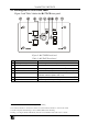
Using Your Media / Room Controller 5 Using Your Media / Room Controller1 The example in Figure 5 shows a front view perspective of a typical RC-7LCE configuration.
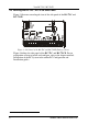
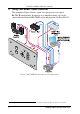
Using Your Media / Room Controller The example in Figure 6 shows a rear view perspective of a typical RC-7LCE configuration. It connects to the power amplifier directly, and to the projector via RS-232, as well as to two relay items (a screen and a lighting system).
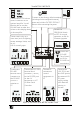
Using Your Media / Room Controller VCR DVD Amplifier Figure 7: Example of a Typical Setup in the Lecture Auditorium 10 KRAMER: SIMPLE CREATIVE TECHNOLOGY
Using Your Media / Room Controller 5.1 Operating the RC-7LC / RC-7LCE In the example defined in Table 3, the buttons—ON, OFF, PC, DVD and VCR—are programmed by the system integrator to perform several tasks1. Table 3: The Commands Configuration ON Button Macro Sequence 1. Power up the projector 2. Power up the DVD 3. Power up the VCR 4. Roll down the projector screen OFF Button Macro Sequence 1. Turn the lights on 2. Power down the projector 3. Stop the DVD 4.
Flash Memory Upgrade 5.3 An Example of Operating the RC-7LC / RC-7LCE Figure 8 shows an example of how to operate the RC-7LC / RC-7LCE: ON DVD PC VCR Select the DVD input on the projector and play the DVD. Select the PC input on the projector and resume the slide show. Select the VCR input on the projector and show the video film. PC Select the PC input on the projector and show the last few slides of the presentation.
Flash Memory Upgrade 6.1 Downloading from the Internet You can download the up-to-date file1 from the Internet. To do so: 1. Go to our Web site at http://www.kramerelectronics.com and download the file: “SetKFRXXX-xx.zip” from the technical support section. 2. Extract the file “SetKFRXXX-xx.zip” package, which includes the KFR-Programmer application setup, the .s19 firmware file and the Web Applet dat file, to a folder (for example, C:\Program Files\KFR Upgrade). 3. Install the KFR-Programmer Application.
Technical Specifications 2. Select the required COM Port1. 3. Click the File button to select the .s19 firmware file included in the package. 4. Click the Send button to download the file. The Send button lights red. 5. Wait until downloading is completed and the red Send button turns off. 6. Disconnect the power on the RC device. 7. Set the PROGRAM switch to OFF. 8. Connect the power on the RC device.
LIMITED WARRANTY Kramer Electronics (hereafter Kramer) warrants this product free from defects in material and workmanship under the following terms. HOW LONG IS THE WARRANTY Labor and parts are warranted for seven years from the date of the first customer purchase. WHO IS PROTECTED? Only the first purchase customer may enforce this warranty. WHAT IS COVERED AND WHAT IS NOT COVERED Except as below, this warranty covers all defects in material or workmanship in this product.
For the latest information on our products and a list of Kramer distributors, visit our Web site: www.kramerelectronics.com, where updates to this user manual may be found. We welcome your questions, comments and feedback. Safety Warning: Disconnect the unit from the power supply before opening/servicing. Caution Kramer Electronics, Ltd. Web site: www.kramerelectronics.com E-mail: info@kramerel.