
User Manual

KRAMER: SIMPLE CREATIVE TECHNOLOGY
Defining the RC-74DL Master Room Controller
6
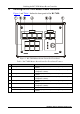
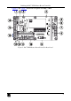
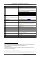
Table 2: RC-74DL Master Room Controller Rear Panel Features
#
Feature
Function
1
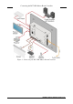
ETHERNET RJ-45 Connector
Connects to the PC or other serial controller through
computer LAN
2
RESET TO DEFAULT
1
Button
Caution: The current LCD text and all button actions will
be erased
Push to erase Push
2
to erase all custom programming and
reset to the factory default definitions
3
:
IP Address:
192.168.1.39
Mask:
255.255.0.0
Gateway:
0.0.0.0
3
PROGRAM (USB) Connector
Connect to a computer for firmware upgrade or for
uploading the configuration file
4
IR IN built-in IR receiver
Use to learn the IR commands from a machine’s remote
control transmitter
5
Power Supply 2-pin Terminal Block
Connector
Connect to power supply (see Section 5.1).
Connect GND to GND, +12V to +12V
6
K-NET TERM Switch
4
Slide to the left (in the direction of the arrow) for K-NET
termination, slide to the right up to leave bus unterminated
7
K-NET1 Connector
Connect the GND pin to the Ground connection
5
; pin B (-)
and pin A (+) are for RS-485, and the +12V pin is for
powering the unit
8
K-NET2 Connector
Connect the GND pin to the Ground connection5; pin B (-)
and pin A (+) are for RS-485, and the +12V pin is for
powering the unit
9
Ring Tongue Terminal Grounding Screw
Connect to grounding wire (optional), (see Section 6)
10
GP I/O Terminal Blocks (1 and 2)
Connect to various sensors, switches, LEDs, or relays
11
Rel (Relay) Terminal Blocks
Connect to low-voltage relay-driven devices (from 1 to 4)
12
Switch
For internal factory use only
13
RS-485 Termination Switch
Slide down for RS-485 termination
6
with 120; slide up for
no RS-485 Line Termination
14
RS-485 Terminal Block Connector
Connect to the RS-485 detachable terminal block on a
switcher or PC
15
RS-232 Terminal Blocks
Connect to the RS-232 devices (from 1 to 3)
16
IR Output Terminal Blocks
Connect to IR emitter cables (from 1 to 2)
1
This operation should be carried out by authorized Kramer technical personnel or by an external system integrator, and
requires removal of the device from the wall by unscrewing the four wall mount screws
2
Using a small screwdriver
3
Disconnect the power and then connect it while pressing the Factory Reset button. The unit will power up and load its
memory with the factory default definitions
4
The last physical device on a K-NET bus must be terminated
5
The ground connection is sometimes connected to the shield of the RS-485 cable (in most applications, it is not connected)
6
The first and the last units on the RS-485 line should be terminated (ON). Other units should be unterminated (OFF)