
User Manual

Contents
i
Contents
1 Introduction 1
2 Getting Started 1
3 Overview 2
3.1 Achieving the Best Performance 3
3.2 Safety Instructions 3
3.3 Recycling Kramer Products 3
4 Defining the RC-74DL Master Room Controller 4
5 Connecting the RC-74DL Master Room Controller 7
5.1 Connecting the RS-232 Interface 9
5.2 Connecting the Ethernet Port 9
6 Grounding the RC-74DL Master Room Controller 10
7 Operating the RC-74DL Master Room Controller 10
8 Front Panel Button Caps and Labels 11
8.1 Installing the Front Panel Button Caps, Labels 14
9 Technical Specifications 15
Figures
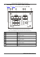
Figure 1: RC-74DL Master Room Controller Front Panel 4
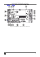
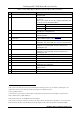
Figure 2: RC-74DL Master Room Controller Rear Panel 5
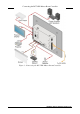
Figure 3: Connecting the RC-74DL Master Room Controller 8
Figure 4: RS-232 Connection 9
Figure 5: Grounding Connection Components 10
Figure 6: Sample Button Label Sheet 13
Figure 7: Button Cap Orientation 14
Figure 8: Button Cap Orientation with Label 14
Figure 9: Placing the Button Cap 14
Tables
Table 1: RC-74DL Master Room Controller Front Panel Features 4
Table 2: RC-74DL Master Room Controller Rear Panel Features 6
Table 3: Grounding Component Descriptions 10
Table 4: RC-74DL Master Room Controller Technical Specifications 15