K R A ME R E LE CT R O N IC S L TD .
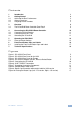
Contents 1 Introduction 1 2 2.1 2.2 2.3 3 3.1 3.2 Getting Started Achieving the Best Performance Safety Instructions Recycling Kramer Products Overview The RC-63DLN Room Controller Front Panel The RC-63DLN Room Controller Rear Panel 2 2 2 3 4 5 6 4 4.1 4.2 4.3 Connecting the RC-63DLN Room Controller Connecting RS-232 Devices Connecting the K-NET Port Grounding the RC-63DLN 10 11 11 11 5 5.1 6 6.
1 Introduction Welcome to Kramer Electronics! Since 1981, Kramer Electronics has been providing a world of unique, creative, and affordable solutions to the vast range of problems that confront video, audio, presentation, and broadcasting professionals on a daily basis.
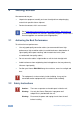
2 Getting Started We recommend that you: Unpack the equipment carefully and save the original box and packaging materials for possible future shipment Review the contents of this user manual i 2.1 Go to http://www.kramerelectronics.com/support/product_downloads.asp to check for up-to-date user manuals, application programs, and to check if firmware upgrades are available (where appropriate).
2.3 Recycling Kramer Products The Waste Electrical and Electronic Equipment (WEEE) Directive 2002/96/EC aims to reduce the amount of WEEE sent for disposal to landfill or incineration by requiring it to be collected and recycled. To comply with the WEEE Directive, Kramer Electronics has made arrangements with the European Advanced Recycling Network (EARN) and will cover any costs of treatment, recycling and recovery of waste Kramer Electronics branded equipment on arrival at the EARN facility.
3 Overview The Kramer RC-63DLN is available as a 2 Gang wall plate for the USA or a 2 Gang wall plate for Europe. It features 6 front panel buttons designed in two groups; one group of 2 buttons, and another group of 4 buttons. Each group can be programmed according to the user's requirements. The RC-63DLN has two LCD labels, letting you program the required group label, as well as rolling text on the display.
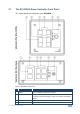
3.1 The RC-63DLN Room Controller Front Panel This section defines the front panel of the RC-63DLN. Figure 1: RC-63DLN Front Panel # 1 Feature 6 Configurable Buttons Function A 2-button group and a 4-button group. Function is programmed by the K-Config Configuration software 2 2 LCD Labels LCD on a blue background, displays up to 8 characters at once (programmed via the USB port).
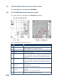
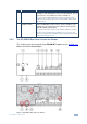
3.2 The RC-63DLN Room Controller Rear Panel This section defines the rear panel of the RC-63DLN. 3.2.1 The RC-63DLN Rear Panel Version for the USA This section shows the rear panel of the RC-63DLN USA version. Figure 2: RC-63DLN Rear Panel for the USA # 1 Feature Grounding Screw Function Connect to grounding wire (optional), see Section 4.3 2 RELAY Ports 2 relay connections (REL 1 and REL 2).
# 10 Feature Function K-NET TERM Switch Slide upwards (in the direction of the arrow) for K-NET termination, slide downwards to leave bus unterminated. The last physical device on a K-NET bus must be terminated You can reach the KNET termination switch by inserting a small screwdriver into the gap between the rear panel PCB and the metal rear panel cover. 11 RESET TO DEFAULT Button Disconnect the power and then connect it while pressing the RESET TO DEFAULT button (using a small screwdriver).
Figure 4 shows the location of the Reset to Default button: Figure 4: RC-63DLN European Version, Reset to Default Button # 1 Feature Grounding Screw Function Connect to grounding wire (optional), see Section 4.3 2 RELAY Ports 2 relay connections (REL 1 and REL 2).
3.2.3 Accessing the RC-63DLN Reset to Default Button To reset to the factory default settings, disconnect the power and then connect it while pressing the RESET TO DEFAULT button (using a small screwdriver). The unit will power up and load its memory with the factory default KNET ID auxiliary setting (ID=2). i This operation should be carried out by authorized Kramer technical personnel or by a qualified system integrator.
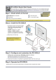
4 Connecting the RC-63DLN Room Controller ! Always switch off the power to each device before connecting it to your RC-63DLN. After connecting your RC-63DLN, connect its power and then switch on the power to each device. To connect the RC-63DLN, as shown in the example in Figure 5, do the following: 1. Connect the RELAY terminal block connectors as follows: Connect REL 1 and COM to the screen Connect REL 2 (for example, to a lighting system, not shown in Figure 5) 2.
4.1 Connecting RS-232 Devices You can control an AV device such as a projector by connecting them to the RC-63DLN via their RS-232 connection. To connect a device to the RC-63DLN via RS-232: Using a straight cable, connect pin 2 to TX, pin 3 to RX and pin 5 to GND on the RS-232 terminal block connector of the RC-63DLN 4.2 Connecting the K-NET Port The K-NET port is wired as shown in Figure 6.
To ground the RC-63DLN: 1. Connect the Ring Tongue terminal to the building grounding point wire (it is recommended to use a green-yellow AWG#18 (0.82mm2) wire, crimped with a proper hand-tool). 2. Insert the M3x6 screw through the toothed lock washers and the tongue terminal in the order shown above. 3. Insert the M3x6 screw (with the two toothed lock washers and ring tongue terminal) into the grounding screw hole and tighten the screw.
5 Operating the RC-63DLN You can operate your RC-63DLN via the front panel buttons or remotely by AUX. keypad over K-NET. The front panel buttons are configured using the K-Config software. For instructions on using the software, see the K-Config Software Guide available from our Web site www.kramerelectronics.com. i 5.1 Note that by default the RC-63DLN is set up as an auxiliary device. Reset to Default Settings To reset to the default settings for the European version: 1.
6 Front Panel Button Caps and Labels The RC-63DLN is supplied with a button label sheet and 16 clear, button caps to house the labels. Figure 8 illustrates a sample button label sheet.
RC-63DLN – Front Panel Button Caps and Labels 15
Figure 8: Sample Button Label Sheet 16 RC-63DLN - Front Panel Button Caps and Labels
6.1 Installing the Front Panel Button Caps and Labels To install the button caps and labels: 1. Remove the required labels from the supplied button label sheet. 2. Hold the button cap so that it is oriented as shown in Figure 9 with the “wings” on the left and right sides for the USA version.
7. Place the faceplate on the RC-63DLN so that the four screw mounting holes are aligned. 8. Insert the four mounting screws and tighten with a screwdriver. 9. Install the volume control knob.
7 Technical Specifications PORTS: 1 RS-232 on terminal block connectors 2 K-NET on terminal block connectors 1 USB port OUTPUTS: 2 relays on terminal block connectors (36V AC or DC, 2A, 60VAC maximum on non-inductive load) 1 IR emitter on terminal block connectors POWER SOURCE: US version: 12V DC, 210mA European version: 12V DC, 385mA OPERATING 0° to +40°C (32° to 104°F) TEMPERATURE: STORAGE TEMPERATURE: HUMIDITY: -40° to +70°C (-40° to 158°F) DIMENSIONS: WEIGHT: USA version: 11.4cm x 2.6cm x 11.
For the latest information on our products and a list of Kramer distributors, visit our Web site where updates to this user manual may be found. We welcome your questions, comments, and feedback. Web site: www.kramerelectronics.com E-mail: info@kramerel.