K R A ME R E LE CT R O N IC S L T D .
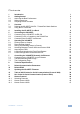
Contents 1 Introduction 1 2 2.1 2.2 2.3 3 3.1 3.2 Getting Started Achieving the Best Performance Safety Instructions Recycling Kramer Products Overview Defining the VS-88DTP 8x8 DVI - Twisted Pair Matrix Switcher Using the IR Transmitter 2 2 2 3 4 5 8 4 Installing the VS-88DTP in a Rack 5 5.1 5.2 5.3 6 6.1 6.2 6.3 6.4 6.5 6.6 6.
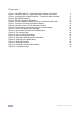
Figures Figure 1: VS-88DTP 8x8 DVI - Twisted Pair Matrix Switcher Front Panel Figure 2: VS-88DTP 8x8 DVI - Twisted Pair Matrix Switcher Rear Panel Figure 3: Connecting the VS-88DTP 8x8 DVI - Twisted Pair Matrix Switcher Figure 4: RS-485 DIP-switches Figure 5: RS-485 Termination DIP-switch Figure 6: Control of Multiple VS-88DTP Devices via RS-232 and RS-485 Figure 7: Local Area Connection Properties Window Figure 8: Internet Protocol (TCP/IP) Properties Window Figure 9: Preset Number Assignments using the Se
1 Introduction Welcome to Kramer Electronics! Since 1981, Kramer Electronics has been providing a world of unique, creative, and affordable solutions to the vast range of problems that confront the video, audio, presentation, and broadcasting professional on a daily basis.
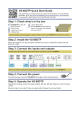
2 Getting Started We recommend that you: Unpack the equipment carefully and save the original box and packaging • materials for possible future shipment • Review the contents of this user manual • Use Kramer high performance high resolution cables i 2.1 Go to http://www.kramerelectronics.com to check for up-to-date user manuals, application programs, and to check if firmware upgrades are available (where appropriate).
2.3 Recycling Kramer Products The Waste Electrical and Electronic Equipment (WEEE) Directive 2002/96/EC aims to reduce the amount of WEEE sent for disposal to landfill or incineration by requiring it to be collected and recycled. To comply with the WEEE Directive, Kramer Electronics has made arrangements with the European Advanced Recycling Network (EARN) and will cover any costs of treatment, recycling and recovery of waste Kramer Electronics branded equipment on arrival at the EARN facility.
3 Overview The VS−88DTP is a high−performance matrix switcher for DVI signals. The unit accepts up to eight DVI inputs, reclocks and equalizes the signals, and routes to any or all DGKat™ twisted pair outputs simultaneously for connection to compatible TP receivers, for example, the PT-572HDCP+ or TP-574. More specifically, the VS-88DTP features: • A maximum data rate of 4.95Gbps (1.
• A worldwide power supply of 100-240V AC • A standard 19” rack mount size of 1U with included rack “ears” Note: The VS-88DTP requires STP (shielded twisted pair) cable. For optimum range and performance, use Kramer's BC-DGKat524, BC-DGKat623 or BC-DGKat7a23 cables. The transmission range depends on the signal resolution, graphics card and display used. The distance using non-Kramer CAT 5, CAT 6, and CAT 7 cables may not reach these ranges.
6 Figure 1: VS-88DTP 8x8 DVI - Twisted Pair Matrix Switcher Front Panel VS-88DTP – Overview 6 # Feature Function 1 IR LED Lights yellow when receiving a signal from an IR remote control 2 IR Sensor IR remote control signal receiver 3 POWER LED Lights green when the device is powered on 4 ALL Button Press to select all outputs (see Section 6.1) 5 OFF Button Press to disconnect one or all outputs (see Section 6.
VS-88DTP – Overview Figure 2: VS-88DTP 8x8 DVI - Twisted Pair Matrix Switcher Rear Panel # 14 Feature IN 1 to IN 8 DVI Input Connectors Function Connect to the DVI sources 15 OUT 1 to OUT 8 RJ-45 TP Output Connectors Connect to the TP receivers (for example, PT-572HDCP+ and TP-574) 16 RS-232 9-pin D-sub (F) Connect to a PC or other serial remote controller 17 PROG TERM 2-way DIP-switch DIP-switch 1 Sets the RS-485 bus termination (see Section 5.2.2) Up = Off, Down = On.
3.2 Using the IR Transmitter You can use the RC-IR3 IR transmitter to control the machine via the built-in IR receiver on the front panel or, instead, via an optional external IR receiver (Model: C-A35M/IRR-50). The external IR receiver can be located up to 15 meters away from the machine. This distance can be extended to up to 60 meters when used with three extension cables (Model: C-A35M/A35F-50).
4 Installing the VS-88DTP in a Rack This section provides instructions for rack mounting the unit.
5 Connecting the VS-88DTP i Always switch off the power to each device before connecting it to your VS-88DTP. After connecting your VS-88DTP, connect its power and then switch on the power to each device. To connect the VS-88DTP as illustrated in the example in Figure 3: 1. Connect up to eight DVI sources (for example, computer graphics sources) to the IN 1 to IN 8 DVI connectors. You do not have to connect all the sources. 2.
Figure 3: Connecting the VS-88DTP 8x8 DVI - Twisted Pair Matrix Switcher 5.1 Connecting to the VS-88DTP via RS-232 You can connect to the VS-88DTP via an RS-232 connection using, for example, a PC. Note that a null-modem adapter/connection is not required.
5.2 Connecting a PC or Controller to the RS-485 Port You can operate the VS-88DTP via the RS-485 port from a distance of up to 1200m (3900ft) using any device equipped with an RS-485 port (for example, a PC). For successful communication, you must set the RS-485 machine number and bus termination.
Figure 4: RS-485 DIP-switches DIP-switches 1, 2, 3 and 4 determine the RS-485 machine number of the VS-88DTP. Machine Number 5.2.
Figure 5: RS-485 Termination DIP-switch 5.2.3 Connecting and Controlling Multiple VS-88DTP Devices You can daisy-chain up to 16 VS-88DTP devices with operation via RS-232 from a PC or serial controller (see Figure 6). To daisy-chain up to 16 VS-88DTP devices: 1. Connect the RS-232-1 port on the first VS-88DTP device to the PC (see Section 5.1). Alternatively, the RS-485 port could be used for PC control. 2.
Figure 6: Control of Multiple VS-88DTP Devices via RS-232 and RS-485 5.3 Connecting the VS-88DTP via Ethernet You can connect the VS-88DTP via Ethernet using a crossover cable (see Section 5.3.1) for direct connection to the PC, or a straight-through cable (see Section 5.3.2) for connection via a network hub or network router. After connecting the Ethernet port, you have to install and configure your Ethernet Port.
4. Select Properties. The Local Area Connection Properties window appears. 5. Select the Internet Protocol (TCP/IP) and click the Properties Button (see Figure 7). Figure 7: Local Area Connection Properties Window 6. Select Use the following IP Address, and fill in the details as shown in Figure 8. 7. Click OK.
5.3.2 Connecting to the Ethernet Port via a Network Hub You can connect the Ethernet port of the VS-88DTP to the Ethernet port on a network hub or network router, via a straight through cable with RJ-45 connectors.
6 Operating the VS-88DTP This section describes how to: 6.1 • Route inputs to outputs (see Section 6.1) • Disconnect outputs (see Section 6.2) • Store and recall a setup (see Section 6.3) • Switch between Protocol 2000 and Protocol 3000 (see Section 6.4) • Acquire the EDID (see Section 6.5) Routing Inputs to Outputs To route an input to an output: 1. Press the required OUT key. 2. Press the required IN key. The selected input is routed to the output. To route one input to all outputs: 1.
6.3 Storing and Recalling Setups in Presets You can use the STO and RCL buttons to store and recall up to 16 setups in presets. Figure 9 illustrates the preset assignment numbers. Preset 1 is assigned to OUT 1 and preset 16 is assigned to IN 8. Note: The preset numbers do not appear on the buttons. Figure 9: Preset Number Assignments using the Selector Buttons To store a setup: 1. Route inputs and outputs as required. 2. Press the STO button. The STO button flashes. 3.
6.5 Acquiring the EDID You can acquire the EDID from: 6.5.1 • A single connected output (see Section 6.5.1) • Several outputs (see Section 6.5.2) • The default EDID (see Section 6.5.3) Acquiring an EDID from a Single Output To acquire or change the EDID from a single output: 1. Connect the acceptor to the required output from which you want to acquire the EDID. 2. Press the EDID button. The EDID button flashes. 3. Press the SELECT IN button to which the EDID will be copied.
4. Press the SELECT OUT button from which the first EDID will be acquired (for example, OUT 1). 5. Press the SELECT IN 1 button again. The IN 1 button ceases to flash. 6. Press another SELECT IN to which the next EDID will be copied (for example, IN 3). The selected input number flashes on the display. 7. Press the SELECT OUT button from which the next EDID will be acquired (for example, OUT 6). 8. Press the SELECT IN 3 button again. The IN 3 button ceases to flash. 9.
6.6 Locking and Unlocking the Front Panel Buttons To lock and unlock the front panel buttons: 1. Press and hold the LOCK button until the buttons lights. The front panel buttons are locked. 2. Press and hold the LOCK button until the button no longer lights. The front panel buttons are unlocked. 6.7 Control Configuration via the Ethernet Port To control several units via the Ethernet, connect the Master unit (Machine # 1) via the Ethernet port to the LAN port of your PC.
7 Controlling the VS-88DTP Remotely via Ethernet You can remotely operate the VS-88DTP using a Web browser via the Ethernet connection (see Section 7.1). To be able to do so, you must use a supported Web browser; Microsoft (V6.0 and higher), Chrome, Firefox (V3.0 and higher). To check that Java is installed and running, browse to: http://www.java.com/en/download/help/testvm.xml This page runs a test and displays a Java success (see Figure 10) or failure message.
2. Enter the unit’s IP number (for the default IP address, see Figure 11) or name in the Address bar of your browser. If you are using DHCP, you have to enter the name. Figure 11: Entering the IP Number in the Address Bar The Loading page appears.
Figure 13: First Time Security Warning 3. Click Run. The main switching control page is displayed which shows a graphical representation of the front panel (see Figure 14). There are two remote operation Web pages: • Main switching matrix (see Section 7.2) • Configuration (see Section 7.3) Select a page by clicking on the relevant link on the left hand side of the window.
7.2 The Main Switching Matrix Page Figure 14: Main Switching Matrix Page The main switching matrix page allows you to: 7.2.1 • Switch any input to any/all outputs independently (see Section 7.2.1) • Operate the unit in the Offline mode (see Section 7.2.2) • Use presets to store and recall switching configurations (see Section 7.2.3) • Lock or unlock the unit’s front panel buttons (see Section 7.2.
Figure 15: Selecting a Switching Point on the Matrix A blue switching icon and Out 4. appears indicating that the channel is switched to In 1 2. Repeat the above steps for each channel that you want to switch. 7.2.2 Operating in the Offline Mode By default, the unit operates in the At-Once mode, meaning that any switching changes take effect immediately. In the Offline mode, changes only take effect when you press the Take button. To operate in the Offline mode: 1. Click the red Offline button.
Figure 16: Switching in the Offline Mode 3. If required, repeat Step 2 for several channels. 4. Click either Take to accept the change or Cancel. 5. Click the Online button to exit the Offline mode. 7.2.3 Storing and Recalling Setups You can store switching configurations in presets and recall them at any time. To store a switching configuration: 1. From the Preset drop-down list, select a preset (in this example, Preset 07).
Figure 17: Selecting Preset 07 2. Click Store. A confirmation message appears. 3. Click OK. The configuration is stored in Preset 07. To recall a setup: 1. From the Preset drop-down list, select a preset (in this example, Preset 03). Presets that contain a configuration are displayed with a blue background; presets with no configuration have a white background. When you select a preset that contains a configuration, the Recall button changes from gray to dark blue.
Figure 18: Selecting Preset 03 2. Click Recall. A confirmation message appears. 3. Click OK. The configuration from Preset 03 is loaded. Note: You can also recall a preset in the Offline mode (see Figure 19) and make it active when you press the Take button (see Section 7.2.2).
7.2.4 Locking the Front Panel Buttons You can lock the front panel buttons to prevent tampering. To lock the front panel buttons: • Click the padlock icon Note: Locking the front panel buttons does not disable remote operation of the unit via Ethernet, RS-232 or RS-485. 7.3 The Configuration Page The Configuration page lets you edit the IP-related settings and only view the others. Editable fields have a white background.
The following fields can be viewed: • Model • Serial Number • Firmware Version • MAC Address To edit the IP-related settings: 1. Edit the required field. 2. Click Submit. The Network Settings confirmation message appears. 3. Click OK. A message appears showing that the settings have been successfully changed. 4. If the IP address was changed or you selected DHCP, reload the Web page using the new name or IP address.
8 Technical Specifications INPUTS: 8 DVI (not HDCP compliant), 1.2Vpp on DVI Molex 24−pin female connectors; DDC signal 5Vpp (TTL) OUTPUTS: 8 DGKat twisted pair on RJ−45 connectors MAX. DATA RATE: 6.75Gbps (2.25Gbps per graphic channel) COMPLIANCE WITH STANDARDS: Supports DVI 1.
9 Default Communication Parameters EDID EDID data is passed between Output 1 and Input 1 RS-232 Protocol 2000 Protocol 3000 (Default) Baud Rate: 9600 Baud Rate: 115,200 Data Bits: 8 Data Bits: 8 Stop Bits: 1 Stop Bits: 1 Parity: None Parity: None Command Format: HEX Command Format: ASCII Example (Output 1 to Input 1): 0x01, 0x81, 0x81, 0x81 Example (Output 1 to Input 1): #AV 1>1 Switching Protocol P2000 -> P3000 Command: P3000 -> P2000 0x38, 0x80, 0x83, 0x81 Command: #P2000
10 Default EDID Each input on the VS-88DTP is loaded with a factory default EDID. Monitor: Model name Manufacturer Plug and Play ID Serial number Manufacture date ------------------------EDID revision Input signal type Color bit depth Display type Screen size Power management Extension blocs ------------------------DDC/CI VS-88DTP KRM KRM0200 1 2006, ISO week 12 1.3 Digital (DVI) Undefined RGB color 700 x 390 mm (31.
Report Information: Date generated Software revision Data source Operating system 21-Jun-11 2.53.0.861 File 5.1.2600.2.
11 Updating the VS-88DTP Firmware Instructions for upgrading the VS-88DTP firmware can be found at http://www.kramerelectronics.com.
12 Table of ASCII Codes for Serial Communication (Protocol 3000) The following table lists the ASCII video signal codes that switch an input to an output for a single VS-88DTP machine in Protocol 3000. For more detailed information, see Section 14.2.
13 Hex Codes for Serial Communication (Protocol 2000) The Hex codes listed in this section are used to set video channels for a single machine (set as Machine 1) connected via either RS-232 or Ethernet. Similar hex codes are used when the VS-88DTP is connected via RS-485 and the machine is set to number 2.
14 Kramer Protocol By default, the VS-88DTP is set to protocol 3000 (see Section 14.2) but is also compatible with Kramer’s Protocol 2000 (see Section 14.3). You can download our user-friendly “Software for Calculating Hex Codes for Protocol 2000” from the technical support section on our Web site at: http://www.kramerelectronics.com Section 14.1 describes how to switch between protocol 3000 and protocol 2000. 14.
14.2.1.2 Command String Formal syntax with commands concatenation and addressing: Start Address Body Delimiter # Destination_id@ Command_1 Parameter1_1,Parameter1_2,…| Command_2 Parameter2_1,Parameter2_2,…| Command_3 Parameter3_1,Parameter3_2,…|… CR 14.2.2 Device Message Format Start Address (optional) Body delimiter ~ Sender_id@ Message CR LF 14.2.2.
Device address (Optional when directly connected to the device) K-NET Device ID or MACHINE NUMBER followed by '@' (ex. #02@ CRLF ) Query sign '?' follows some commands to define a query request. All outputs sign '*' defines all outputs.
starting character and the message closing character only once, at the beginning of the string and at the end. Commands in the string do not execute until the closing character is entered. A separate response is sent for every command in the chain. 14.2.7 Maximum String Length 64 characters 14.2.8 Backward Support You can switch between protocols using a switch protocol command from either platform. The following tables list instruction codes for Protocol 3000.
Basic routing commands Note: When AFV mode is active, this command will switch also video. Read video connection VID? OUT Short form: V? OUT VID? * VID IN>OUT VID IN>1, IN>2, … Parameter Description: IN = Input number or '0' to disconnect output. '>' = Connection character between in and out parameters. OUT = Output number or '*' for all outputs.
Preset commands Command Syntax Parameters Description: PRESET = Preset number. OUT = Output in preset to show for, '*' for all.
Identification commands Command Read machine name Reset machine name to factory default* Syntax NAME? NAME-RST Response NAME MACHINE_NAME NAME-RST MACHINE_FACTORY_NAME RESULT *Note: machine name not equal to model name. This name relevance for site viewer identification of specific machine or for network using (with DNS feature on). MACHINE_NAME = Up to 14 Alfa-Numeric chars. * Machine factory name = Model name + last 4 digits from serial number.
14.3 Kramer Protocol 2000 The Kramer Protocol 2000 RS-232/RS-485 communication uses four bytes of information as defined below. MSB 0 7 1st byte 1 7 2nd byte 1 7 3rd byte 1 7 4th byte LSB DESTINATION D 6 INSTRUCTION N5 5 N4 4 N3 3 N2 2 N1 1 N0 0 INPUT I6 6 I5 5 I4 4 I3 3 I2 2 I1 1 I0 0 OUTPUT O6 6 O5 5 O4 4 O3 3 O2 2 O1 1 O0 0 OVR 6 X 5 MACHINE NUMBER M4 M3 4 3 M2 2 M1 1 M0 0 1st BYTE: Bit 7 – Defined as 0.
Instruction Codes for Protocol 2000 Instruction Definition for Specific Instruction # Input 0 1 Description RESET VIDEO SWITCH VIDEO 3 STORE VIDEO STATUS 4 5 16 RECALL VIDEO STATUS REQUEST STATUS OF A VIDEO OUTPUT REQUEST WHETHER SETUP IS DEFINED / VALID INPUT IS DETECTED ERROR / BUSY 30 LOCK FRONT PANEL 15 31 56 61 62 0 Set equal to video input that is to be switched (0 = disconnect) Set as SETUP # Set as SETUP # Set as SETUP # SETUP # or Input # For invalid / valid input (i.e.
NOTE 6 – If INPUT is set to 127 for these instructions, then, if the function is defined on this machine, it replies with OUTPUT=1. If the function is not defined, then the machine replies with OUTPUT=0, or with an error (invalid instruction code). If the INPUT is set to 126 for these instructions, then, if possible, the machine will return the current setting of this function, even for the case that the function is not defined.
For the latest information on our products and a list of Kramer distributors, visit our Web site where updates to this user manual may be found. We welcome your questions, comments, and feedback. Web site: www.kramerelectronics.com E-mail: info@kramerel.