K R A ME R E LE CT R O N IC S L T D .
Contents 1 Introduction 1 2 2.1 Getting Started Achieving the Best Performance 2 2 3 Overview 3 4 Your SPK-C612 Closed-back Ceiling Speakers 4 5 5.1 5.2 5.3 5.
1 Introduction Welcome to Kramer Electronics! Since 1981, Kramer Electronics has been providing a world of unique, creative, and affordable solutions to the vast range of problems that confront video, audio, presentation, and broadcasting professionals on a daily basis.
2 Getting Started We recommend that you: • Unpack the equipment carefully and save the original box and packaging materials for possible future shipment • Review the contents of this user manual • Use Kramer high-performance high-resolution cables i 2.1 Go to http://www.kramerelectronics.com to check for up-to-date user manuals, application programs, and to check if firmware upgrades are available (where appropriate).
3 Overview The SPK-C612 consists of a pair of high performance closed back speakers. The pair can be mounted on the ceiling, as well as via a ceiling mounting kit used to safely secure the speakers to the ceiling. The SPK-C612 speakers feature a diameter of 6.5”, a resistance of 8Ω and a closed-back depth of 7”.
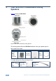
4 Your SPK-C612 Closed-back Ceiling Speakers Figure 2 defines the SPK-C612: Figure 2: SPK-C612 Closed-back Ceiling Speaker The following table defines the SPK-C612 hardware items (per speaker pair) for each model in the series: Description A pair of ceiling speakers (one shown) Two grilles (one shown) Cutout template This table defines the ceiling mounting kit items: Four support ring screws 4 Two ceiling support rings (C-ring) – one shown Two pairs of tile rails – one of a pair shown SPK-C612 - Y
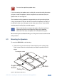
Each Closed-back Ceiling speaker is supported by a C-ring and two tile rails. The tile rails prevent the speakers from falling if the tile itself comes out or falls apart, as their ends catch onto the T-grid. When mounting onto the ceiling tiles, use both supports. When mounting onto a sheetrock ceiling, the C-ring alone is used to reinforce the ceiling material. i Be sure that the tiles can support the speaker. Smaller sized tiles or fiberglass-type tiles cannot support the weight of the speakers.
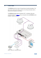
5 Installing the SPK-C612 Closed-back Ceiling Speakers This section explains how to install the SPK-C612, that is: 5.1 • Choosing the best place to locate your speakers (see Section 5.1) • Cutting the ceiling tile (see Section 5.2) • Mounting the Speakers (see Section 5.3) • Painting the speakers (see Section 5.4) Choosing the Best Location Ideally, locate the speakers above the main listening area.
! Do not nail or staple the speaker wires. If you are mounting the speakers onto a ceiling tile, remove the ceiling tiles where you plan to install the speakers. Use the template to trace and then cutout the speaker hole over an empty box. The closed-back ceiling speakers are supported by the ceiling mounting kit (two C-rings and two pairs of tile rails; the tile rails prevent the speakers from falling if the tile itself comes out or falls apart, as their ends catch onto the T-grid).
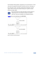
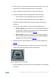
2. Place the tile rails on the tile and snap them into the two tabs on the C-ring. Align the rails so that the ends extend over the T-channel grid. 3. Insert a screw through each tab on the C-ring to secure the rails. 4. Connect the speaker wires to the appropriate connector terminals: PIN 1 and PIN 2 are connected internally and are positive (+) PIN 3 and PIN 4 are connected internally and are negative (-) Screw the hold-down screws on the connector until tight, using a small screwdriver.
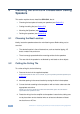
8. Tighten the mounting tabs by turning the screw counter clockwise (see Figure 6). The first quarter turn, rotates the tab outwards, and the following turns tighten the tabs to the rear side of the ceiling surface When tightening the mounting tabs, the tabs automatically turn outward, thus clamping the speaker to the wall from its rear side. Note: Do not over-tighten the screws. It may cause damage to both the speakers and the surface. Figure 6: Tighten the Mounting Tabs 9.
11. Install the grilles to the speakers: Push the grille fastener into the hole in front of the baffle Press the grille into place until the front of the grille is flush with the rim of the baffle i 5.4 Check that the grille is securely seated To remove the grille, insert two bent paper clips into the holes in the grille and carefully pull it down. Repeat this around the perimeter of the grille until it is completely removed.
6 Technical Specifications Audio and Power DESCRIPTION: 2-way co-axial low-profile ceiling speakers with metal back can HIGH FREQUENCY DRIVER: 1" MYLAR dome tweeter LOW FREQUENCY DRIVER: 6.5” Polypropylene cone with rubber edge woofer IMPEDANCE: 8Ω DISPERSION COVERAGE: 80° CROSSOVER FREQUENCY: 3kHz NOMINAL SENSITIVITY: 87dB SPL @1m, 1W DIRECTIVITY FACTOR (Q): 5.1 (averaged 100Hz – 10kHz); 6.2 (2kHz) DIRECTIVITY INDEX (DI): 6.8dB (averaged 100Hz – 10kHz); 5.
! P/N: ! " 2900- 300187 " Rev: 1