
User's Manual

Your VP-727T Presentation Switcher Control Panel
3
Enables special effect transitions between two sources via a robust T-bar
(used for manual control of transition speeds). Alternatively, the effect can be
implemented via a TAKE button, with a potentiometer to set the transition speed
Features single button access to all inputs
1
—both for the Preview and for the
Program output—and the buttons have removable transparent caps to allow labeling
Features dedicated single button actions for special effect selection,
immediate freezing and blanking, PIP display, and the choice of wipe direction
Has the user menu—conveniently located on the VP-727T panel—for
complete control of the VP-727
via its Preview OSD
Consol can be simultaneously connected to up to four VP-727
machines.
Control communication is via the RS-485 port, thus allowing the panel to be
located more than 1km from each VP-727
Has an RS-232 port for field upgrading of its firmware
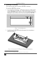
With its angled faceplate, may be used freestanding on a table, or
mounted in a desktop or in a 19” rack (when your switcher is rack-mounted
near to the source devices, you can conveniently place the VP-727T
on a table
or desk away from the equipment rack)
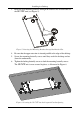
Has a gooseneck lamp (included) that can be plugged into the consol for
use in low lighting environments
Is powered by a 12V DC source
To achieve the best performance:
Connect only good quality connection cables
Avoid interference from neighboring electrical appliances, make sure not
to block the ventilation holes and position your VP-727T
away from moisture,
excessive sunlight and dust. Be sure to position it straight in the correct
horizontal position on the table, desk or rack
Caution – No operator-serviceable parts inside unit.
Warning – Use only the Kramer Electronics input power
wall adapter that is provided with this unit
2
.
Warning – Disconnect power and unplug unit from wall
before installing or removing device or servicing unit.
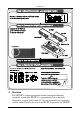
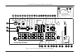
4 Your VP-727T Presentation Switcher Control Panel
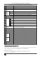
Figure 1 and Table 1 define the front panel of the VP-727T:
1 Has two sets of input buttons: one that routes the input to the "PROGRAM" output and the other that routes to the
"PREVIEW" output
2 For example: model number AD2512C, part number 2535-000251