Kramer Electronics, Ltd.
Contents Contents 1 2 2.1 3 3.1 4 5 6 6.1 6.2 6.3 6.4 Introduction Getting Started Quick Start Overview About HDMI Your VP-725xl Presentation Switcher / Scaler Installing in a Rack Connecting the VP-725xl Presentation Switcher / Scaler Connecting the VP-725xl The RGBS and RGsB PINOUTs Connecting to the VP-725xl via RS-232 Connecting the VP-725xl via the ETHERNET port 1 1 1 3 5 5 10 11 11 13 13 14 7 7.1 7.2 7.3 7.4 7.5 8 8.
Contents Figures Figure 1: VP-725xl Presentation Switcher / Scaler Front Panel Figure 2: VP-725xl Presentation Switcher / Scaler Rear Panel Figure 3: Connecting the VP-725xl Presentation Switcher / Scaler Figure 4: Crossed Cable RS-232 Connection Figure 5: Straight Cable RS-232 Connection with a Null Modem Adapter Figure 6: Local Area Connection Properties Window Figure 7: Internet Protocol (TCP/IP) Properties Window Figure 8: MENU Items Figure 9: Input Screen Figure 10: Picture Screen Figure 11: Output Sc
Contents Table 22: Technical Specifications of the HDMI Input Signal (for RGB or YUV Colorspace) 38 Table 23: Technical Specifications of the Component Input Signal 38 Table 24: Technical Specifications of the RGBHV/Comp/YPbPr Output Signal 38 Table 25: Communication Protocol of the VP-725xl 40 Table 26: The Error Codes 52 iii
Introduction 1 Introduction Welcome to Kramer Electronics! Since 1981, Kramer Electronics has been providing a world of unique, creative, and affordable solutions to the vast range of problems that confront the video, audio, presentation, and broadcasting professional on a daily basis. In recent years, we have redesigned and upgraded most of our line, making the best even better! Our 1,000-plus different models now appear in 11 groups1 that are clearly defined by function.
Getting Started 2 KRAMER: SIMPLE CREATIVE TECHNOLOGY
Overview 3 Overview The VP-725xl is a presentation scaler/switcher with multiple signal format sections. The unit has five independent 4x1 video sections: composite, s-Video (Y/C), component (YUV), computer graphics, and HDMI, plus a single USB input. It also scales any video input up or down to a selectable graphics or HDTV output resolution and provides glitch-free switching between sources through FTB™ (fade-thru-black) switching technology.
Overview • • • • • • • • • • • • • Supports embedded audio on the HDMI inputs and outputs1 Features Projector Anywhere™ technology – horizontal & vertical geometry controls that compensate for off-axis projector placement Supports a wide choice of computer graphics output resolutions up to WUXGA/1080p, plus user-definable custom output resolutions2 with selectable refresh rates Provides multiple aspect ratio selections: standard, letterbox, follow output, virtual wide, follow input, and user definable se
Your VP-725xl Presentation Switcher / Scaler 3.1 About HDMI High-Definition Multimedia Interface (HDMI) is an uncompressed all-digital1 audio/video interface, widely supported in the entertainment and home cinema industry. It delivers the highest high-definition image and sound quality. Note that Kramer Electronics Limited is an HDMI Adopter and an HDCP Licensee.
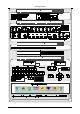
Your VP-725xl Presentation Switcher / Scaler Figure 1: VP-725xl Presentation Switcher / Scaler Front Panel 6 KRAMER: SIMPLE CREATIVE TECHNOLOGY
Your VP-725xl Presentation Switcher / Scaler Table 1: Front Panel VP-725xl Presentation Switcher / Scaler Features # 1 2 3 4 5 6 7 8 Feature INPUT SELECTOR Buttons MODE SELECT Buttons Function YC CV Selects one of the s-Video (Y/C) sources (from 1 to 4) Selects one of the CV sources (from 1 to 4) UXGA Selects one of the UXGA sources (from 1 to 4) HDMI USB COMP VIDEO GROUP Selects one of the HDMI sources (from 1 to 4) 1 Press to select the USB source Selects one of the component video sources (from
Your VP-725xl Presentation Switcher / Scaler Figure 2: VP-725xl Presentation Switcher / Scaler Rear Panel 8 KRAMER: SIMPLE CREATIVE TECHNOLOGY
Your VP-725xl Presentation Switcher / Scaler Table 2: Rear Panel VP-725xl Presentation Switcher / Scaler Features # Feature Function 1 2 3 4 5 6 7 8 9 10 CV IN BNC Connectors CV OUT BNC Connector YC IN 4-pin Connectors YC OUT 4-pin Connector COMP Input G/Y BNC B/Pb Connector R/Pr G/Y COMP OUTPUT B/Pb BNC R/Pr Connector Connects to the composite video sources (from 1 to 4) Connects to the composite video acceptor Connects to the s-Video (Y/C) sources (from 1 to 4) Connects to the s-Video (Y/C) acceptor
Installing in a Rack 5 Installing in a Rack This section provides instructions for rack mounting the unit.
Connecting the VP-725xl Presentation Switcher / Scaler 6 Connecting the VP-725xl Presentation Switcher / Scaler This section describes how to connect the VP-725xl. In particular, how to connect the: • VP-725xl rear panel (see section 6.1) • Interlaced and progressive RGBS and RGsB inputs (see section 6.2) • PC (see section 6.3) • Ethernet port (see section 6.4) Using the VP-725xl you can select any one of the 21 inputs and scale that input to up to three scaled outputs (at the identical resolution). 6.
Connecting the VP-725xl Presentation Switcher / Scaler 5. Connect up to three SCALED OUTPUTS, as follows: Connect the RGBHV connectors (G/Y, B/Pb, R/Pr, H, and V) to the RGBHV acceptor (for example, a projector) Connect the HDMI connector to the HDMI acceptor (for example, an LCD display) Connect the UXGA connector to the UXGA acceptor, for example, a monitor (not illustrated in Figure 3) 6. Connect the power cord1 (not illustrated in Figure 3). 7. If required connect: A PC (see section 6.3).
Connecting the VP-725xl Presentation Switcher / Scaler 6.2 The RGBS and RGsB PINOUTs Table 3 defines the input progressive1 and interlaced2 RGBS and RGsB pinouts: Table 3: RGBS and RGsB PINOUTS Input Color Space PINOUT VGA RGsB Red to PIN 1 Green + sync, to PIN 2 Blue to PIN 3 Red to PIN 1 Green to PIN 2 Blue to PIN 3 Hs (H and V) to PIN 13 Green + sync to Y Blue to Pb Red to Pr RGBS YUV YPbPr 6.
Connecting the VP-725xl Presentation Switcher / Scaler contains all nine wires for a full connection of the D-sub connector. Because the null-modem adapter (which already includes the flow control jumpering described in Method A above) only requires pins 2, 3 and 5 to be connected, you are free to decide whether to connect only these 3 pins or all 9 pins. Figure 5: Straight Cable RS-232 Connection with a Null Modem Adapter 6.
Connecting the VP-725xl Presentation Switcher / Scaler Figure 6: Local Area Connection Properties Window 5. Select Use the following IP Address1, and fill in the details as shown in Figure 7. Figure 7: Internet Protocol (TCP/IP) Properties Window 6. Click OK. 6.4.2 Connecting the ETHERNET Port via a Network Hub (Straight-Through Cable) You can connect the Ethernet port of the VP-725xl to the Ethernet port on a network hub or network router, via a straight-through cable with RJ-45 connectors.
Operating the Presentation Switcher / Scaler 7 Operating the Presentation Switcher / Scaler The VP-725xl includes the following front panel buttons: • A set of 21 INPUT SELECTOR buttons • Video Group and Scaler Mode SELECT buttons • A PIP button • A FREEZE button • A set of 7 OSD buttons (described in Table 1): OSD ON, MENU, ENTER, -, +, UP, and DOWN This section describes how to: • Switch an input to an output (see section 7.1) • Use the PIP feature (see section 7.
Operating the Presentation Switcher / Scaler When selecting a PIP source, the Presentation Switcher / Scaler automatically recognizes and can display the selected graphic PIP source on any video source1 or the selected video source on any graphic1 source, compliant to Table 4.
Operating the Presentation Switcher / Scaler 7.3 Locking and Unlocking the Front Panel To prevent accidental changes to settings or unauthorized tampering with the front panel, you can lock the front panel. To lock the front panel, press and hold the ENTER front panel button1 for about 3 seconds. The front panel buttons are locked2 (except for the ENTER button on the front panel). The LCD displays: Keypad Lock On.
Configuring and Controlling the VP-725xl 8 Configuring and Controlling the VP-725xl This section describes how to configure and control the VP-725xl via the: • OSD menu (see section 8.1) • LCD display (see section 8.2) • Infrared remote control transmitter (see section 8.3) You can also control the VP-725xl via the Ethernet (see section 8.4) 8.
Configuring and Controlling the VP-725xl 8.1.1 The Input Screen Figure 9 and Table 5 define the Input screen.
Configuring and Controlling the VP-725xl 8.1.2 The Picture Screen Figure 10 and Table 6 define the Picture screen.
Configuring and Controlling the VP-725xl 8.1.3 The Output Screen Figure 11 and Table 7 define the Output screen.
Configuring and Controlling the VP-725xl Setting H-Pan 1 V-Pan1 H-Zoom1 V-Zoom 1 Function Selection/Range Default Horizontal pan -16 to 16 0 Vertical pan Horizontal zoom -16 to 16 -8 to 8 0 0 Vertical zoom -8 to 8 0 100%, 150%, 200%, 225%, 250%, 275%, 300%, 325%, 350%, 375%, 400%, Custom 100% Zoom Set the Zoom Custom Zoom3 Set the Zoom Zoom H-Pan4 4 Zoom V-Pan HQV Color Setting 2 From 0 to 32 (this range is equivalent to 100% to 400%) -16 to 16 0 -16 to 16 0 Color saturation Adj
Configuring and Controlling the VP-725xl 8.1.4 The PIP Screen Figure 12 and Table 8 define the PIP screen.
Configuring and Controlling the VP-725xl 8.1.5 The Geometry Screen Figure 13 and Table 9 define the Geometry screen, allowing the user flexibility in positioning his projector relative to the screening surface.
Configuring and Controlling the VP-725xl 8.1.6 The Setup Screen Figure 14 and Table 11 define the Setup screen. Figure 14: Setup Screen Table 11: Setup Screen Functions Setting Function Selection/Range Save Save a profile From Profile 1 to Profile 8 Default Recall Recall a profile From Profile 1 to Profile 8 Slideshow Set speed for slide show (see section 8.1.
Configuring and Controlling the VP-725xl Setting Function EDID EEPROM EDID writing protection Protect HDMI Switch Behavior 8.1.7 Selection/Range 1 Set to DVD/Normal or PC/Bypass Default On/Off Normal2/Bypass Normal The Slideshow Feature The VP-725xl lets you run a slideshow via the USB input and set the slideshow speed via the slideshow feature. To prepare a slideshow: 1. Load the slideshow JPEG3 images to a USB memory stick. The slides will appear in alphabetical order. 2.
Configuring and Controlling the VP-725xl 8.1.7.1 The Advanced Setup Screen Figure 15 to Figure 18, and Table 13 to Table 16 define the Advanced Setup screens. Figure 15: Advanced Setup Screen The Mode Set functions define the desired working resolution and refresh rate when the system cannot distinguish between similar resolutions and refresh rate values (see Table 12).
Configuring and Controlling the VP-725xl Table 14: Misc Functions Setting Function Selection/Range Default Logo Choose ON for the start up logo to appear on the screen OFF for it not to appear Set to Custom to download a custom Logo1 (Flash ROM) On, Off or Custom Kramer Logo (On) Blank Color Set the blank color (the color that Black or Blue appears on the screen when the blank button is pressed) Capture Press to capture the desired image input2 to Flash ROM for using as a logo or as the backgroun
Configuring and Controlling the VP-725xl Figure 17: Input Setup Screen Table 15: Input Functions Setting Function HT Horizontal Total Range 1344 HW Horizontal sync pulse width 136 HS Horizontal active start point 296 HA HP Horizontal active region Horizontal polarity 1024 VT Vertical Total 806 VW Vertical sync pulse width 6 VS Vertical active start point 35 VA Vertical active region 768 VP Vertical polarity OCLK Output clock 65 Press to apply settings off N/A Enable Apply
Configuring and Controlling the VP-725xl Table 16: Output Functions Setting Function HT HW Horizontal total Horizontal sync pulse width Default HS Horizontal active start point 296 HA Horizontal active region 1024 1344 136 HP Horizontal polarity VT Vertical total VW Vertical sync pulse width 6 VS Vertical active start point 35 VA Vertical active region 768 VP Vertical polarity OCLK Output clock Apply Press to apply the settings Set Current Import the values of the currently s
Configuring and Controlling the VP-725xl 8.2 Operating via the LCD Display You can control the VP-725xl from the front panel high contrast LCD Display. You can operate the VP-725xl via the LCD Display, using the: • Front panel OSD buttons: MENU, ENTER, -, +, UP and DOWN • Infrared remote control transmitter (see section 8.3) keys: MENU, and the navigation keys For example, to set the Keystone to 6 via the LCD Display, using the front panel buttons, do the following: 1.
Configuring and Controlling the VP-725xl Table 17: Infrared Remote Control Transmitter Functions PIP PIP Size SWAP Key Function Freeze Pauses the output video Power Cycles power Blank Toggles between a blank screen (blue or black screen) and the display Mute N/A MIX N/A Talk Over N/A Over Ride N/A Audio Level N/A Video Group Select the Video group operation mode Audio Group N/A Auto-Image VOL OSD Picture Enter Menu VOL + Capture USB VGA HDMI CV YC Scaler Master Audio Sele
Using Text Overlay 8.4 Operating via ETHERNET/Serial Port To control your VP-725xl via the Ethernet/Serial Port: • Connect the ETHERNET port of the VP-725xl to the Ethernet port of your PC1 • Download the Ethernet Application from our Web site on http://www.kramerelectronics.com • Install and configure the Ethernet Application 9 Using Text Overlay The text overlay feature is accessed via the Application Program (AP)2.
Using Text Overlay Table 18: Features and Functions of the TextOverlay Application Feature Function Parameter Setting Area Text Color Dropdown Box Select the Text color Background Color Dropdown Box Set the text background color Transparency Dropdown Box Select On for a transparent background or Off for a non-transparent background Set the thickness of the background stripe (72 or 36) Display Height Check Box Text Position – V-Position Set the vertical position of the text background on the display
Technical Specifications 10 Technical Specifications Table 19 includes the technical specifications: 1 Table 19: Technical Specifications of the VP-725xl Presentation Switcher / Scaler INPUTS: 4 x CV 1Vpp/75Ω on BNC connectors; 4 x YC 1Vpp (Y); 0.3Vpp (C)/75Ω on 4-pin connectors; 4 x Component (Y/G, Pb/B, Pr/R or RGsB2) on BNC connectors; 4 x VGA (VGA through UXGA, RGBS or RGsB3) on 15-pin HD connectors; 4 x HDMI on HDMI connectors GROUP OUTPUTS: 1x CV 1Vpp/75Ω on a BNC connector; 1 x YC 1Vpp (Y); 0.
Technical Specifications Table 20: Technical Specifications of the RGBHV / RGBS (PC) / RGsB (PC) Input Signal1 Resolution Vertical Frequency (Hz) Notes Resolution Vertical Frequency (Hz) Notes 640x480 (480p) 60 VESA 1152x870 75 Mac21 640x480 67 Mac13 1152x900 66 Sun 640x480 72 VESA 1152x900 76 Sun 640x480 75 VESA 1280x720 60 VESA 640x480 85 VESA 1280x800 60 VESA 720x400 70 1280x960 60 VESA 720x400 85 VESA 1280x960 85 VESA 800x600 56 VESA 1280x768 60 VESA 80
Technical Specifications Table 23: Technical Specifications of the Component Input Signal Resolution Vertical Frequency (Hz) Remark 1080i 60 1080i 50 YPbPr 1080p 60 YPbPr 1080p 50 YPbPr 720p 720p 60 50 YPbPr YPbPr YPbPr 480i 60 YPbPr 480p 60 YPbPr 576i 50 YPbPr 576p 50 YPbPr Table 24: Technical Specifications of the RGBHV/Comp/YPbPr Output Signal 38 Resolution Vertical Frequency (Hz) Remark Resolution Vertical Frequency (Hz) Remark 640x480 60 VESA 1366x768 60 VESA
VP-725xl Communication Protocol 11 VP-725xl Communication Protocol Communication Confirmation: Send: CR Reply: CR> Set and Get command: Set Command: YControl_TypeFunctionParamCR Reply: ZControl_TypeFunctionParamCR> Get Command: YControl_TypeFunctionCR Reply: ZControl_TypeFunctionParamCR> Example 1 (select VGA1 as video input channel): "Y01570CR" "Z01570CR>" Example 2 (get selected current input channel): "Y 1157CR" "Z 11570CR>" (0 = VGA 1) Definition: : ASCII Code 0x20 CR:
VP-725xl Communication Protocol Table 25 includes the Communication Protocol: Table 25: Communication Protocol of the VP-725xl Control Type Set Get Function Parameter 0: Auto 1: RGB 2: YUV 0: Auto 1: NTSC 2: PAL 3: PAL-M 4: PAL-N 5: NTSC 4.
VP-725xl Communication Protocol Control Type Set Get Function 0 1 25 0 1 26 0 1 27 0 0 0 0 1 1 1 1 28 29 30 31 Parameter 0 : Native HDMI 1 : 640x480@60Hz 2 : 640x480@75Hz 3 : 800x600@50Hz 4 : 800x600@60Hz 5 : 800x600@75Hz 6 : 1024x768@50Hz 7 : 1024x768@60Hz 8 : 1024x768@75Hz 9 : 1280x768@50Hz 10: 1280x768@60Hz 11.
VP-725xl Communication Protocol Control Type Set Get Function Parameter Description 0 1 32 0 0 0 1 1 1 33 34 35 0 1 36 0 1 37 0 1 38 0 1 39 0 0 0 0 1 1 1 1 40 41 42 43 0 1 44 0 1 45 0 1 49 0: 100% 1: 150% 2: 200% 3: 225% 4: 250% 5: 275% 6: 300% 7: 325% 8: 350% 9: 375% 10: 400% 11: Custom 0 ~ 32 -16 ~ 16 -16 ~ 16 0: Off 1: On 0: Picture-In-Picture 1: Picture + Picture 2: Split 0: VGA1 1: VGA2 2: VGA3 3: VGA4 4: HDMI1 5: HDMI2 6: HDMI3 7: HDMI4 8: COMP1 9: COMP2 10: COMP3 11:
VP-725xl Communication Protocol Control Type Set Get Function Parameter Description 0 1 53 0 1 54 0 1 55 0 1 56 0 1 57 0 0 0 0 0 1 1 1 1 1 58 59 60 61 62 0: Dynamic 1: User Define 0~340 (step 2) 0: No audio 1: VGA1 2: VGA2 3: VGA3 4: VGA4 5: HDMI1 6: HDMI2 7: HDMI3 8: HDMI4 9: COMP1 10: COMP2 11: COMP3 12: COMP4 13: YC1 14: YC2 15: YC3 16: YC4 17: CV1 18: CV2 19: CV3 20: CV4 0: Keystone 1: Anyplace 2: Rotation 0: Front 1: Ceiling 2: Rear 3: Rear ceiling -40 ~ 40 -30~30 -2000~2000 -2000
VP-725xl Communication Protocol Control Type Set Get Function 0 - 0 1 74 0 - 1 75 76 0 1 77 0 1 78 0 1 79 0 1 80 0 1 81 0 1 82 0 - 83 0 1 84 0 1 85 0 1 86 0 1 87 0 1 88 0 1 89 0 1 90 0 1 91 0 0 0 0 - 92 93 94 95 44 73 Parameter 0: Profile 1 1: Profile 2 2: Profile 3 3: Profile 4 4: Profile 5 5: Profile 6 6: Profile 7 7: Profile 8 0: Off 1: On N/A N/A 0: 1400x1050x60 1: 1680x1050x60 0: 1280x1024x75 1: 1280x1024x76 0: Center 1: Top Left 2: Top Right
VP-725xl Communication Protocol Control Type Set Get Function 0 0 0 0 0 - 96 97 98 99 100 0 1 101 0 1 102 - 1 103 Parameter Description N/A N/A N/A N/A N/A 0: Off 1: On 0: Off 1: On 0: 640x480 60 1: 640x480 67, Mac13 2: 640x480 72 3: 640x480 75 4: 640x480 85 5: 720x400 70 6: 720x400 85 7: 800x600 56 8: 800x600 60 9: 800x600 72 10: 800x600 75 11: 800x600 85 12: 832x624 75, Mac16 13: 1024x768 60 14: 1024x768 70 15: 1024x768 75 16: 1024x768 75, Mac19 17: 1024x768 85 18: 1024x800 84, Sun 19: 115
VP-725xl Communication Protocol Control Type Set Get - 46 1 Function 104 Parameter 48: 1080p 24 49: 1280x800 60 50: 1440x900 60 51: 1440x900 60(R) 52: 1280x768 (R) 53: 1680x1050 60 (R) 54: 1366x768 60 55: 1366x768 60 (R) 94: Custom1 95: Custom2 96: Custom3 97: Custom4 98: No Input detected 99: other 101: NTSC 102: PAL 103: PAL-M 104: PAL-N 105: NTSC 4.
VP-725xl Communication Protocol Control Type Set Get Function 0 0 0 1 1 1 105 106 107 0 1 108 0 1 109 0 0 0 1 1 1 110 111 112 0 1 113 0 1 114 0 0 1 1 115 116 0 1 117 0 0 0 0 1 1 1 118 119 120 121 0 1 122 Parameter 36: 1080p 60 37: 1080p 50 38: 720p 60 39: 720p 50 40: 480i 41: 480p 42: 576i 43: 576p 44: 1280x800 60 (R) 45: 1920x1200 60 46: 1920x1080 60 47: 1280x720 60 48: 1080p 24 49: 1280x800 60 50: 1440x900 60 51: 1440x900 60(R) 52: 1280x768 60(R) 53: 1680x1050 60 (R) 54: 1
VP-725xl Communication Protocol Control Type Set Get Function 0 1 123 0 0 0 1 1 1 124 125 126 0 1 127 0 1 128 0 0 0 0 1 1 - 129 130 131 132 0 1 135 0 1 136 0 1 137 0 1 138 0 1 139 0 1 140 0 0 0 0 0 - 141 142 143 144 145 0 1 146 0 1 147 0 1 148 0 0 48 1 1 151 152 Parameter 0: Negative polarity 1: Positive polarity 384~2047 2~(HS-13) 15~(VT-VA-1) 480~1200 <= (VT-16) 0: Negative polarity 1: Positive polarity 25 < OCLK < 165 25 < OCLK < 165 N/A N/A 0: Follo
VP-725xl Communication Protocol Control Type Set Get Function Parameter Description Select HDMI group channel Note : Error when SELECT ≠ Video Group / Audio Group / AV Group Select COMP group channel Note : Error when SELECT ≠ Video Group / Audio Group / AV Group Select YC group channel Note : Error when SELECT ≠ Video Group / Audio Group / AV Group Select CV group channel Note : Error when SELECT ≠ Video Group / Audio Group / AV Group 0 1 153 0: HDMI1 1: HDMI2 2: HDMI3 3: HDMI4 0 1 154 0: COMP1
VP-725xl Communication Protocol Control Type Set Get Function 0 1 173 0 1 174 0 - 175 0 - 176 0 - 177 0 - 178 0 1 179 0 - 180 0 - 181 0 - 182 - 183 - 184 - 185 - 186 - 187 - 188 - 189 - 190 - 191 - 192 - 193 - 194 0 0 0 0 0 0 0 0 0 0 0 0 50 Parameter Description Hot key PIP source select, same as remote control key - PIP Source Hot key PIP size, same as remote control key 0: 1/25 (for Get Command) 1: 1/16 (for Get Command) - PIP Size 2: 1/9 (for Ge
VP-725xl Communication Protocol Control Type Set Get Function 0 0 0 0 0 0 1 1 1 1 1 1 195 196 197 198 199 200 0 1 201 0 1 202 0 1 203 0 1 204 11.
LIMITED WARRANTY Kramer Electronics (hereafter Kramer) warrants this product free from defects in material and workmanship under the following terms. HOW LONG IS THE WARRANTY Labor and parts are warranted for seven years from the date of the first customer purchase. WHO IS PROTECTED? Only the first purchase customer may enforce this warranty. WHAT IS COVERED AND WHAT IS NOT COVERED Except as below, this warranty covers all defects in material or workmanship in this product.
For the latest information on our products and a list of Kramer distributors, visit our Web site: www.kramerelectronics.com, where updates to this user manual may be found. We welcome your questions, comments and feedback. Safety Warning: Disconnect the unit from the power supply before opening/servicing. Caution Kramer Electronics, Ltd. Web site: www.kramerelectronics.com E-mail: info@kramerel.